GMR_Board(SKU_DFR0271) - jimaobian/DFRobotWiki GitHub Wiki
Introduction
This is a generic mobile robot control board. The GMR board supports up to 3 microcontrollers, two Arduino Nano and one Arduino Mega or Mega ADK. One of Nano is used to control the motors and their encoders, the other is used to drive 6 URM sensors. The Main microcontroller is the Mage or Mega ADK, it is used to collect the date and work out the control logic. The GMR has two wireless slots available which allow Xbee, blueteeth/Wifi to be used at the same time.
 "wikilink") "wikilink") |
Note: The lastest version has been compatible with the newest Arduino Nano V3 & V4. |
Specification
- Operating Voltage (logic level) 5 V & 3.3V
- Input Voltage (recommended) 12-23 V
- Input Voltage (limits) 9-26 V
- Digital I/O Pins 8
- Analog Input Pins 8
- DC Current: 10A@5V
Diagram


category: Product Manual category: DFR Series category: MicroControllers
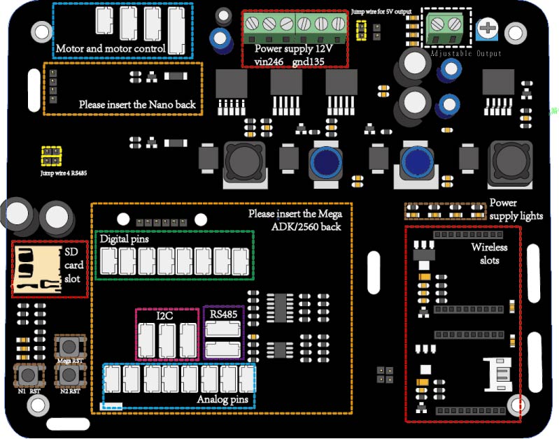
Motor and motor control 
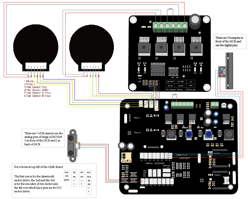
This part includes some I/O pins of one of the Nano controllers which could be put into the GMR. The users can use them to connect the encoder and two kinds of motor controllers, D10 and D9 with a GND pin can be used for Saber tooth motor controller another 6pins together D9 D10 D8 with VCC and GND used for DC Motor Driver 2×15A - Lite D2 –D6 are used for the encoders.
Nano slots 
There are 2 Nano slots on the GMR. For general mobile robot, this two micro controllers can help you to solve the motor control and driver some special sensors. And they all have connected with the main micro controller Mega ADK or Mega 2560. The communication way is the I2C.
Mega ADK/2560 
The main controller of this GMR board. Because of the high performance of the Arduino Mega ADK/2560. For the GMR, 8 I/O and 8 analog pins can be used. 3 groups of I2C pins can communicated with other controllers and 2 groups of RS485 belongs to another nano controller。
SD card slot 
Extra memory for the Mega
Wireless slots 
Two wireless slots available which allow Xbee, blusteeth/Wifi to be used at the same time.
Adjustable output 
An adjustable output
Power Supply 
use 2 4 6 pins for Vin and 1 3 5 pins for GND Input Voltage (recommended) 7-20 V
Diagram N2
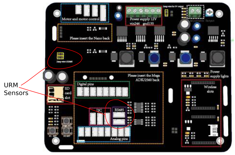
On board Nano2 is connected to the I2C stream, and (with jumpers plugged in) to the URM sensors via 485 protocol. GMR board integrates a 485 protocol encoder/decoder, and our URM ultrasonic sensors are also capable, thus allowing for an array of Ultrasound sensors to be connected. Nano on socket 2 will then process this information accordingly. If you wish, you can unplug the jumpers and directly connect 485 with jumper wires, to other pins, Allowing a different controller to drive the Ultrasound sensors. 