DFR0057_flash_uploader - jimaobian/DFRobotWiki GitHub Wiki
Introduction
If you want to update a new version of the firmware here is what you need to do
Pin out diagram
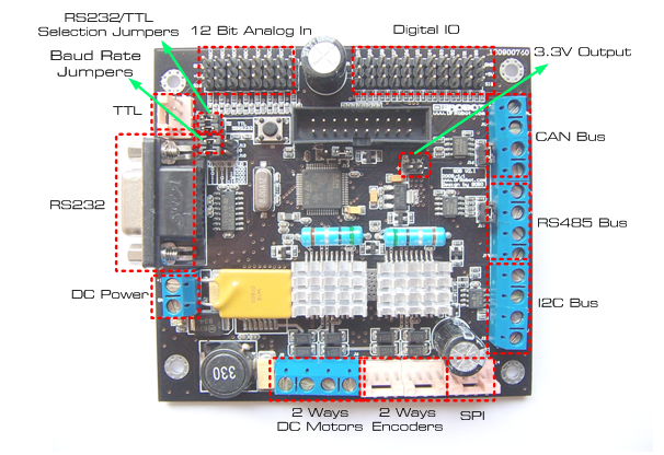
Pin Definition
Select boot loader pins J13, position 1-2. It is not marked on the Diagram but its right on top of the micro controller.
Applying Power
 to power the sdb boards, simply connect the ground wire from your supply to the screw terminal labeled “gnd”, and then connect the positive wire from your supply to the screw terminal labeled “+12v”. nOTE: DO NOT apply voltage over 15V DC.
Serial hardware configuration
 the sdb board supports rs232/ttl interface. the rs232/ttl output mode is selected by jumpers. the flash loader tool should be configured with parity even, echo disabled and timeout 5. your COM port and the baud rate 115200 (check jumper selection is right )
Tutorial
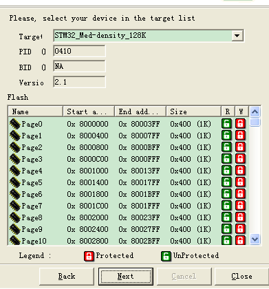
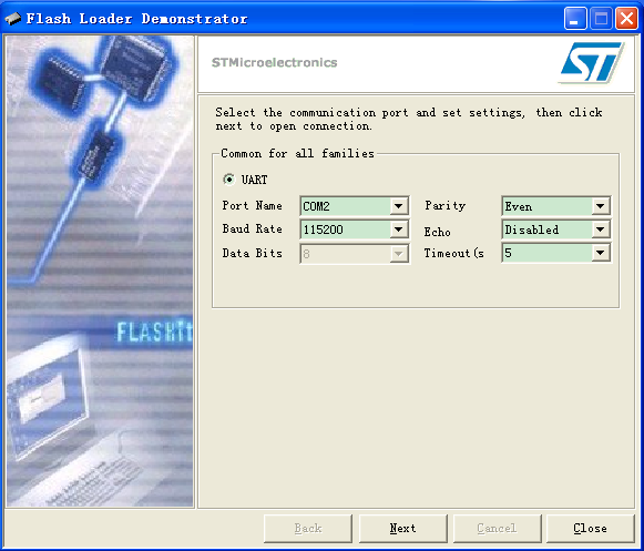 after you have connected serial, applied power and configured the board you should be able to click next
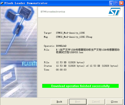
 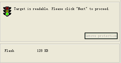 proceed and open the new window to select the new firmware version.
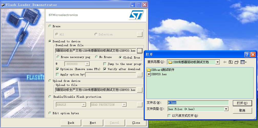
Trouble Shooting
Other resources
 shopping sensor/motor drive board - version 2.3 (sku:dfr0057)
category: Product Manual category: DFR Series category: Motor Controllers