CO2_Sensor_SKU_SEN0159 - jimaobian/DFRobotWiki GitHub Wiki
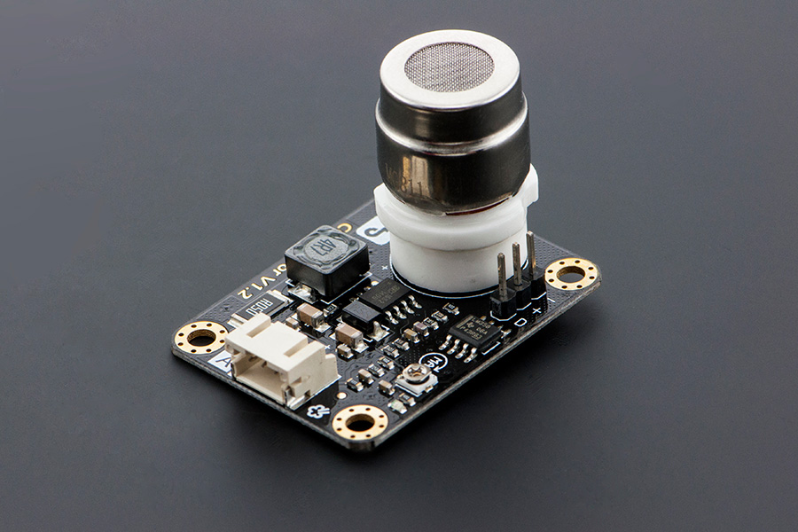
Greenhouse Effect is melting the iceberg every minute,. By knowing the exact concentration of CO2, we can do something to reduce the CO2 and to protect our earth. For that reason, a HQ CO2 sensor is designed by DFRobot engineer . This is the first CO2 sensor in OSHW market. The output voltage of the module falls as the concentration of the CO2 increases. The potentiometer onboard is designed to set the threshold of voltage. As long as the CO2 concentration is high enough (voltage is lower than threshold), a digital signal (ON/OFF) will be released.
- Features:
- It has MG-811 sensor module onboard which is highly sensitive to CO2 and less sensitive to alcohol and CO, Low humidity & temperature dependency.
- Onboard heating circuit brings the best temperature for sensor to function. 5V power input will be boosted to 6V for heating.
- This sensor has an onboard conditioning circuit for amplifying output signal.
- Input Power: 3.3 - 6V@ >500mA (5V recommended)
- Operating voltage: 0 - 5V
- Interface: Analog
- One digital output (Once the CO2 concentration is over the set threshold value, it will output digital HIGH, 5V)
- Onboard heating circuit
- Heating Current: 200mA
- Heating Voltage: 6V
- Heating Power: 1200mW
- Size: 32x42mm
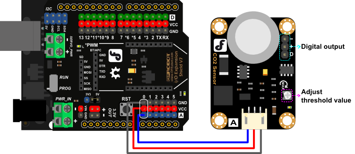
 NOTE: An external power supply 7~12V@>500mA is necessary to feed Arduino card to heat the CO2 Sensor to ensure the CO2 sensor could get enough heating power (3.3V - 6V @ >500mA). Or it won't work properly! The external power is not showed in the diagram.
/*******************Demo for MG-811 Gas Sensor Module V1.1*****************************
Author:  Tiequan Shao: [email protected]
         Peng Wei:     [email protected]
         Modified by Leff from DFRobot, [email protected], 2016-4-21, make the algorithm clearer to user
Lisence: Attribution-NonCommercial-ShareAlike 3.0 Unported (CC BY-NC-SA 3.0)

Note:    This piece of source code is supposed to be used as a demostration ONLY. More
         sophisticated calibration is required for industrial field application.

                                                            Sandbox Electronics    2012-05-31
************************************************************************************/

/************************Hardware Related Macros*********|***************************/
#define         MG_PIN                       (0)     //define which analog input channel you are going to use
#define         BOOL_PIN                     (2)     //Arduino D2-CO2 sensor digital pinout, labled with "D" on PCB
#define         DC_GAIN                      (8.5)   //define the DC gain of amplifier

/***********************Software Related Macros************************************/
#define         READ_SAMPLE_TIMES            (10)     //define how many samples you are going to take in normal operation
#define         READ_SAMPLE_INTERVAL         (50)    //define the time interval(in milisecond) between each samples in
//normal operation

/**********************Application Related Macros**********************************/
//These values differ from sensor to sensor. User should derermine this value.
#define         ZERO_POINT_X                 (2.602) //lg400=2.602, the start point_on X_axis of the curve
#define         ZERO_POINT_VOLTAGE           (0.324) //define the output of the sensor in volts when the concentration of CO2 is 400PPM
#define         MAX_POINT_VOLTAGE            (0.265) //define the output of the sensor in volts when the concentration of CO2 is 10,000PPM
#define         REACTION_VOLTGAE             (0.059) //define the ��voltage drop�� of the sensor when move the sensor from air into 1000ppm CO2

/*****************************Globals***********************************************/
float           CO2Curve[3]  =  {ZERO_POINT_X, ZERO_POINT_VOLTAGE, (REACTION_VOLTGAE / (2.602 - 4))};
//Two points are taken from the curve.With these two points, a line is formed which is
//"approximately equivalent" to the original curve. You could use other methods to get more accurate slope

//CO2 Curve format:{ x, y, slope};point1: (lg400=2.602, 0.324), point2: (lg10000=4, 0.265)
//slope = (y1-y2)(i.e.reaction voltage)/ x1-x2 = (0.324-0.265)/(log400 - log10000)

void setup() {
  Serial.begin(9600);                              //UART setup, baudrate = 9600bps
  pinMode(BOOL_PIN, INPUT);                        //set pin to input
  digitalWrite(BOOL_PIN, HIGH);                    //turn on pullup resistors
  Serial.print("MG-811 Demostration\n");
}

void loop() {
  int percentage;
  float volts;

  volts = MGRead(MG_PIN);
  Serial.print( "SEN0159:" );
  Serial.print(volts);
  Serial.print( "V           " );

  percentage = MGGetPercentage(volts, CO2Curve);
  Serial.print("CO2:");
  if (percentage == -1) {
    Serial.print("Under heating/beyond range(400~10,000)");
  } else {
    Serial.print(percentage);
  }
  Serial.print( "ppm" );

  Serial.print( "       Time point:" );
  Serial.print(millis());
  Serial.print("\n");

  if (digitalRead(BOOL_PIN) ) {
    Serial.print( "=====BOOL is HIGH======" );
  } else {
    Serial.print( "=====BOOL is LOW======" );
  }
  Serial.print("\n");
  delay(1000);
}
/*****************************  MGRead *********************************************
Input:   mg_pin - analog channel
Output:  output of SEN-000007
Remarks: This function reads the output of SEN-000007
************************************************************************************/
float MGRead(int mg_pin) {
  int i;
  float v = 0;

  for (i = 0; i < READ_SAMPLE_TIMES; i++) {
    v += analogRead(mg_pin);
    delay(READ_SAMPLE_INTERVAL);
  }
  v = (v / READ_SAMPLE_TIMES) * 5 / 1024 ;
  return v;
}

/*****************************  MQGetPercentage **********************************
Input:   volts   - SEN-000007 output measured in volts
         pcurve  - pointer to the curve of the target gas
Output:  ppm of the target gas
Remarks: By using the slope and a point of the line. The x(logarithmic value of ppm)
         of the line could be derived if y(MG-811 output) is provided. As it is a
         logarithmic coordinate, power of 10 is used to convert the result to non-logarithmic
         value.
************************************************************************************/
int  MGGetPercentage(float volts, float *pcurve) {
  volts = volts / DC_GAIN;
  if (volts > ZERO_POINT_VOLTAGE || volts < MAX_POINT_VOLTAGE ) {
    return -1;
  } else {
    return pow(10, (volts - pcurve[1]) / pcurve[2] + pcurve[0]);
    volts = 0;
  }
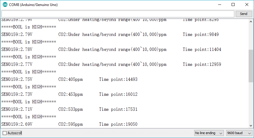
}After about one hour heating process, open Arduino IDE Serial monitor, you could get the stable readings about ambient CO2 density. Breathe to the sensor you could see the data changing. Read more in FAQ>Q5 below.
| '''Q1. '''I pretend a sensor capable of measuring concentrations between 0%-10% (0 - 100.000 ppm) of CO2. What is the measurement range of your device? |
'''A. '''Its detect range is: 400—10000 ppm. You could find its sensitivity and more info in its datasheet.
| '''Q2. '''How to calibrate the sensor to get the correct CO2 density? |
'''A. '''To calibrate the sensor, you needs a CO2 meter which can tell the CO2 density first, like this one. Once you got it, you can calibrate the sensor in its sample code, that is clarified in sample code. The adjustable resistance on CO2 module is not for calibration but for digital alarm signal output. If you don't have relevant equipment to help you to define the two values of the ZERO_POINT_VOLTAGE and REACTION_VOLTGAE, you could just simply use the sample code to get some reference readings.
Sample code:
//These two values differ from sensor to sensor. user should derermine this value.
#define         ZERO_POINT_VOLTAGE           (0.324) //define the output of the sensor in volts when the concentration of CO2 is 400PPM
#define         REACTION_VOLTGAE             (0.020) //define the voltage drop of the sensor when move the sensor from air into 1000ppm CO2
One of our customers adjusted his sensor like this to get his expected readings.
#define         ZERO_POINT_VOLTAGE           (0.535) //define the output of the sensor in volts when the concentration of CO2 is 400PPM (output was 4.6V)
#define         REACTION_VOLTGAE             (0.039) //define the voltage drop of the sensor when move the sensor from air into 1000ppm CO2 (output was 4.21 tuned to .039)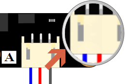
| '''Q3. '''How to know the voltage of the output of the sensor in volts when the concentration of CO2 is *ppm? |
'''A. '''You can use a Voltage Metre to test the module's output voltage from PH2.0-3P connector. Or you could also use Arduino to read its voltage. After you got the voltage, you can divide it by the module's gain, that is 8.5 in the example2.
e.g. if you got 2.754V, then ZERO_POINT_VOLTAGE = 2.754/8.5 = 0.324.
: NOTE:
NOTE:
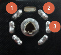
- It is not a good idea to use a Voltage Meter on pin 1 and pin 2 on the back of the sensor. It seems working, but actually, since CO2 sensor has a large built-in resistance, generic voltage metre can not work well in this case.
-
Pin Definition
- GND
- Vout
- Vin: 6V
-
Pin Definition
- When the sensor is in heating process, please wait untill it can output stable readings and test.
| '''Q4. '''Why I can't get an reasonable reading using sample code, I mean the readings are too large, negatives, and not stable at all? |
'''A. ''' Please use a Voltage Meter on pin 1 and pin 3 on the back of the sensor (see picture > "For Q3. note sensor pins on back") to test if the heating voltage is 6V. If not, please go to Connecting Diagram to check the notice. If you have used a valid external power, but even after 48 hours heating process, no valid data was displayed at all no matter how you breathed to the sensor. Then it proves that yours should be defective.
| '''Q5. '''Why I waited over an hour, but still can't get an reasonable reading using sample sketch? |
'''A. ''' After the sensor was stored in Oxidizing condition for some time, the core part would be oxidized in different extent. So it would need some time for the sensor to go through the "heating process" to get real CO2 readings. The "heating process" may cost 0.5~48hrs.
| '''Q6. '''What is the logic of the code below, from the sample code? Why need the exponent of the pow function? |
**************************** MQGetPercentage **********************************
int MGGetPercentage(float volts, float *pcurve)
{
if ((volts/DC_GAIN )>=ZERO_POINT_VOLTAGE) {
return -1;
} else {
return pow(10, ((volts/DC_GAIN)-pcurve[1])/pcurve[2]+pcurve[0]);
}
}
``` |
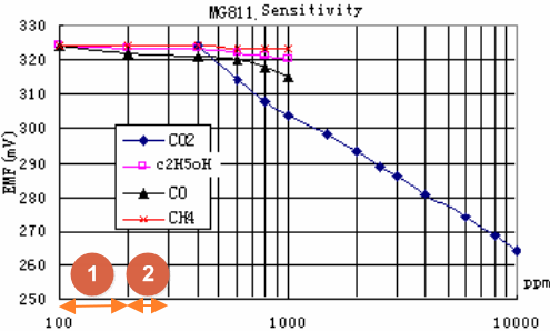
'''A. '''In the sensor's [datasheet](http://www.dfrobot.com/image/data/SEN0159/CO2b%20MG811%20datasheet.pdf), you could found its map describing the relationship between Voltage and CO2 density. And by comparing the two notes (1 & 2) located on X-Aixs, you could easily tell they are not in the same length, that's to say, the PPM was describing as **exponent**. And that's why in the code, it has to use the function **pow** to calculate the real CO2 density.
| |
|----------------------------------------------------------------------------------------------------------------|
| For any questions/advice/cool ideas to share, please visit [**DFRobot Forum**](http://www.dfrobot.com/forum/). |
More
----
 get it from [**dfrobot store**](http://www.dfrobot.com/index.php?route=product/product&product_id=1023#.ukkjzozi1gy) or [**dfrobot distributor**.](http://www.dfrobot.com/index.php?route=information/distributorslogo)
[category: Product Manual](/category:_Product_Manual "wikilink") [category: SEN Series](/category:_SEN_Series "wikilink") [category: Module](/category:_Module "wikilink")
[category: Diagram](/category:_Diagram "wikilink") [category: DFRobot](/category:_DFRobot "wikilink")