Bees_Shield_SKU_DFR0210 - jimaobian/DFRobotWiki GitHub Wiki
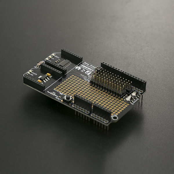
Have you ever been in a situation where you need two communication methods for your project? How about when a serial port is occupied by another serial device, and you still need to setup wireless communication? The DFRobot Bees shield can solve these problems. The Bees shield is compatible with Arduino boards such as UNO R3 and Leonardo it has a large prototyping shield giving you plenty of space to experiment and add extra components to your project. Thanks to its uniform interface, there are a huge number of devices compatible with the xBee socket: xBee, WiFi xBee, Bluetooth Bee, zigBee, etc. The Bees shield is also stackable giving you more flexibility with your projects. Although it is an old design, it is still very practical!
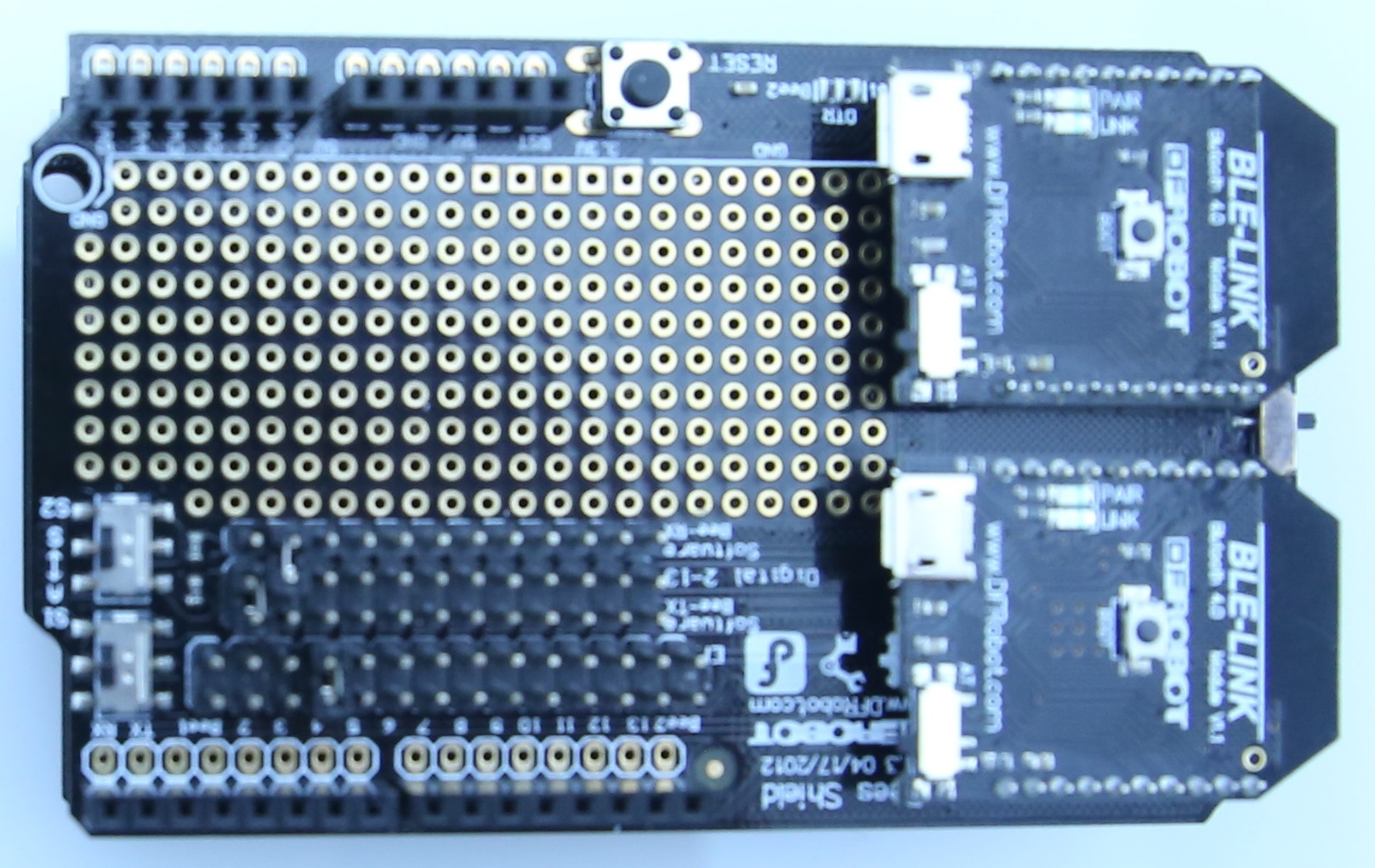
- Operating Voltage: 3.3V~5V
- xBee slots: 2
- Serial port: Hardware Serial port and Software Serial port
- Arduino compatible
- DIP prototyping area
- Dimension: 92 mm * 56 mm/ 3.62 inches * 2.2 inches
|
 Note:
*3. Programmable Switch:
Set the switch to "PROG" when you upload a program
Set the switch to "RUN", when you use the hardware serial port
- 5. xBee TX & RX: The silk-screen shows the xBee RX & TX pins, which connect to the Arduino TX & RX ones. It means if you define D2 as Arduino_RX in the code, you should connect to D2 to xBee_TX on the shield. The same goes for Arduino_TX.
In this Tutorial, we will use two BLE Link modules as wireless modules
| ### Requirements |
-
Hardware
- UNO x1
- Bees Shield x1
- BLE LINK x2
- Android or iOS device x1
-
Software
- Arduino IDE V1.6.5 Click to Download Arduino IDE from Arduino®
- Install the APK file into your Android phone
- Compile the source code into your Apple device
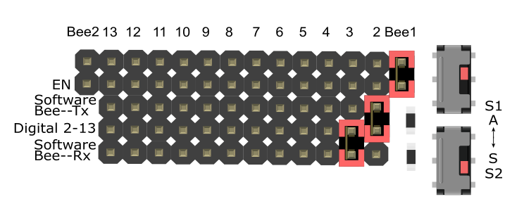
=== Bee1 <==> Hardware Serial Port; Bee2 <==> Software Serial Port ===
| #### Connection Diagram |
If you need Bee1 working with the hardware serial port, and Bee2 working with the software serial port, you can change the jumpers and switches like so:
/*
 # This sample code is used to test the Bees shield.
 # Editor : Mickey
 # Ver    : 1.0
 # Product: Bees shield
 # SKU    : DFR0210
 # The circuit:
   software RX is digital pin 2 (connect to TX of Bee2 device)
   software TX is digital pin 3 (connect to RX of Bee2 device)
*/

#include <SoftwareSerial.h>

SoftwareSerial mySerial(2, 3); // UNO RX -- Bee TX, UNO TX -- Bee RX

void setup()
{
  Serial.begin(115200);
  mySerial.begin(115200);
  delay(50);

}
void loop()
{
  Serial.println("this is Bee1 hardware!");
  mySerial.println("this is Bee2 software!");
  delay(500);
}image:DFR0210-APP1.jpg
image:DFR0210-APP.jpg
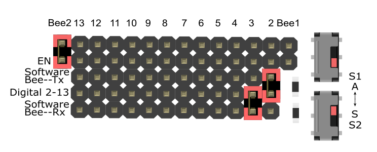
| === Bee2 <==> Hardware Serial Port; Bee1 <==> Software Serial Port === |
If you need Bee1 working with the software serial port, and Bee2 working with the hardware serial port, you can change the jumpers and switches like so:
| #### Sample Code |
/*
 # This sample code is used to test the Bees shield.
 # Editor : Mickey
 # Ver    : 1.0
 # Product: Bees shield
 # SKU    : DFR0210
 # The circuit:
   software RX is digital pin 2 (connect to TX of Bee1 device)
   software TX is digital pin 3 (connect to RX of Bee1 device)
*/

#include <SoftwareSerial.h>

SoftwareSerial mySerial(2, 3); // UNO RX -- Bee TX, UNO TX -- Bee RX

void setup()
{
  Serial.begin(115200);
  mySerial.begin(115200);
  delay(50);

}
void loop()
{
  Serial.println("this is Bee2 hardware!");
  mySerial.println("this is Bee1 software!");
  delay(500);
}image:DFR0210-APP2.jpg
image:DFR0210-APP3.jpg
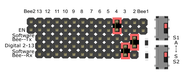
| === Bees <==> Using The Hardware Serial Port Alternately === |
If you need both BLE LINK modules working with the hardware serial port alternately, you can change the jumpers and switches like so:
(You can select a pin from digital 4-12 as the xBee Enable pin to make them work. The following example uses "D4".
/*
 # This sample code is used to test an Arduino hardware serial switch.
 # Editor : Mickey
 # Ver    : 1.0
 # Product: Bees shield
 # SKU    : DFR0210
*/

void setup()
{
  Serial.begin(115200);
  pinMode(4, OUTPUT);
  delay(500);
}
void loop()
{
  digitalWrite(4, LOW);
  Serial.println("this is Bee1 hardware!");
  Serial.println(" ");
  delay(500);

  digitalWrite(4, HIGH);
  Serial.println("this is Bee2 hardware!");
  Serial.println(" ");
  delay(500);
}image:DFR0210-APP1.jpg
image:DFR0210-APP3.jpg
NOTE: The Bees Shield only has three modes above. Currently it is not possible to make two Bees work with the software serial port at the same time. |
There are no questions about this product yet. If you have any problems or suggestions, you are welcome to email us or post on the DFRobot forum!
 For any questions/advice/cool ideas to share, please visit the DFRobot Forum or email [email protected]
 get it from dfrobot store or dfrobot distributor.