BLE_Wireless_Gamepad_(SKU_DFR0304) - jimaobian/DFRobotWiki GitHub Wiki

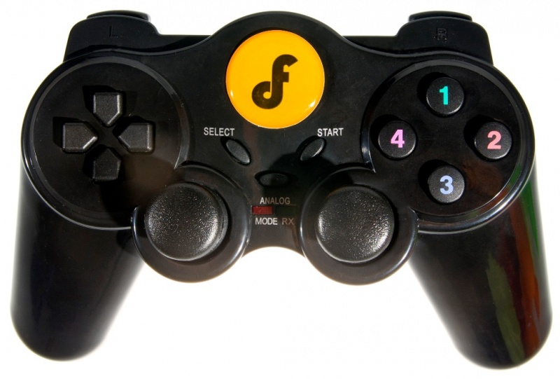
The newly launched BLE Wireless Gamepad by DFRobot is based on BLE chip CC2540 from TI for DIYers. It supports the master-salve machine switch, Bluetooth HID and transparent communication through serial. It allows you to custom your own wireless communication for controlling your robots, mobile platforms, UAVs and etc. It's Pecfect for your projects what need a remote controller.
- Microcontroller: TI CC2540
- 12 digital button outputs
- 4 analog outputs
- Support USB update BLE chip program
- Support Bluetooth HID keyboard, allowing to connect to BLE adapter
- Support Transparent communication through Serial
- Power supply: "AAA" Battery x3 or Micro USB
- Support one-click switch between the master and slave
- Support auto-bind MAC and one-click unbind
- Size: 165mm x 110mm
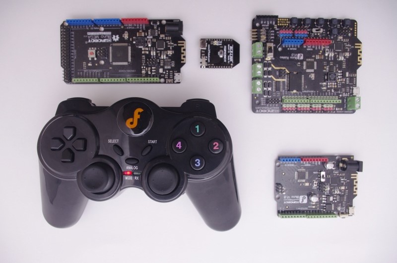
- Compatible with:

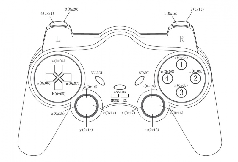
The figure above shows all the buttons and their key values of the gamepad, including:
- 3 control buttons for switching, unbundling, reset, etc
- 4 analog outputs (in HID mode used for buttons and in host mode used for analog output)
In the figure, letters (e.g., "a") and numbers (e.g., "1") represent the key values in HID mode, and the corresponding hexadecimal numbers (such as "0 x20") represent the key values in host mode, where the joystick output are analog values.
- The SELECT Button is used for one-click switching master-slave machine
- ANALOG key is used for one-click unbinding the MAC address when in host mode
- START Button is used to reset
BLE transparent transmission protocol
This protocol is only for making Gamepad as the master to connect with other slave equipment. The data format of the transparent transmission is for reference.
| Frame head | Address | The command length | Joystick position value | Command | Checksum | |
|---|---|---|---|---|---|---|
| 0x55 | 0xaa | 1 byte | 1 byte | 1 byte | n byte | 1 byte |
Description:
The frame head: 0x55 The frame head: 0xaa Address: 1 byte (the default is 0x11) The command length: 1 byte (the number of digital key pressed) Joystick position: 1 byte (the relative position pressed of the analog key) Command: n bytes (digital and analog key values) Checksum: 1 byte
For example:
When there is only one digital key is pressed, such as key "a", and no analog key is pressed, the data transmission format is: 55 AA 11 01 00 04 00 00 00 00 15. Among them "55 AA 11" is the frame head and address, "01" means that the number of digital key pressed is 1, "00" shows there is no change of the relative position of analog keys, and "04" is the digital key value. The four "00" left behind are analog values and there is no change. If there is an ananlog value pressed, the corresponding bit will output data. "15" is a checksum.
When the analog and the digital key are pressed, such as key "a" and "y", output data format is: 55 11 01 08 04 00 00 00 AA 5 e 7 b. Among them "55 AA 11" represents frame head and address, "01" refers to the number digital key pressed, "08" means that the 4th analog key changes, such as "5e". This analog values will change, with the extent of the joystick being pushed (as shown in the following figure). It supports outputing simutaneouly multiple digital and analog values and obtaining the specific analog value changes by identifying the relative position.


When multiple analog keys are pressed, such as key 01 and 02, the output is 03. The algorithm is a bitwise OR on "01" and "02".

#define EN1 5//pin for run the right motor
#define IN1 4//pin for control right motor direction
#define EN2 6//pin for run the left motor
#define IN2 7//pin for control left motor direction

#define FORW 0
#define BACK 1

int databuf[8]={};

void Motor_Control(int M1_DIR,int M1_EN,int M2_DIR,int M2_EN)
{
  if(M1_DIR==FORW)//M1 motor direction
    digitalWrite(IN1,FORW);//forward
  else
    digitalWrite(IN1,BACK);//back
  if(M1_EN==0)
    analogWrite(EN1,LOW);//stop
  else
    analogWrite(EN1,M1_EN);//set speed

  if(M2_DIR==FORW)
    digitalWrite(IN2,FORW);
  else
    digitalWrite(IN2,BACK);
  if(M2_EN==0)
    analogWrite(EN2,LOW);
  else
    analogWrite(EN2,M2_EN);
}

void setup()
{
  pinMode(4,OUTPUT);
  pinMode(5,OUTPUT);
  pinMode(6,OUTPUT);
  pinMode(7,OUTPUT);
  pinMode(13,OUTPUT);
  Serial.begin(115200);
}
void loop()
{
   if (Serial.available())
  {
    for(int i = 0; i < 10; i++)
    {
      databuf[i] = Serial.read();
      delay(2);
    }
    if(databuf[5] == 0x04)
      Motor_Control(1,255,1,255);
    else if(databuf[5] == 0x05)
      Motor_Control(0,255,0,255);
    else if(databuf[5] == 0x06)
      Motor_Control(0,255,1,255);
     else if(databuf[5] == 0x07)
      Motor_Control(1,255,0,255);
     else
        Motor_Control(0,0,0,0);
  }
}