7A_Dual_DC_Motor_Driver_SKU__DRI0041 - jimaobian/DFRobotWiki GitHub Wiki
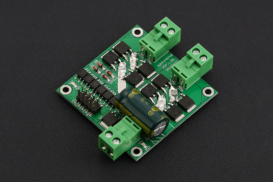
This is an ultra small Dual DC motor driver for some room limited projects. UVLO (Under Voltage Latch-Out) features a safe guard for your system. It is very considerate to own an Photo Coupler isolation for all the signals in case of that the motor's Reverse Current would interfere the control signals. Besides all, all the interfaces includes ESD (electro-static discharge) protection.
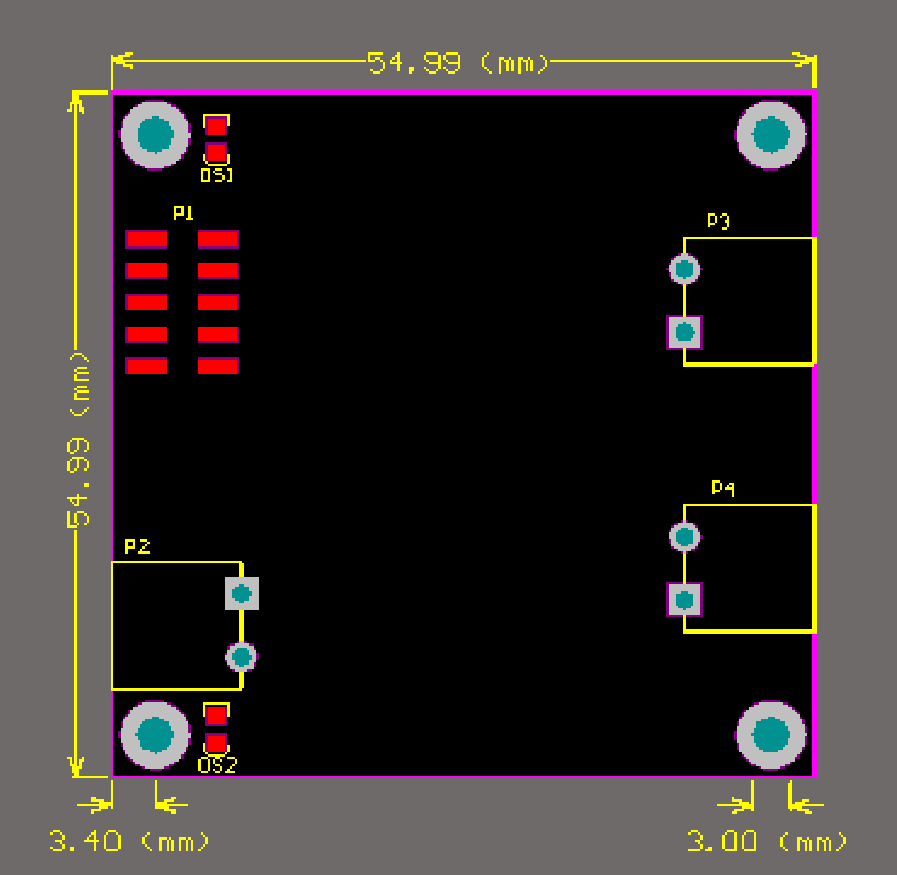
- Voltage supply: DC 7 ~ 24 V
- Voltage supply limit: 6.5 ~ 27 V
- Control signal Level (Compatible 3.3V/5V)
- High: DC 3.0 ~ 6.5 V
- Low: DC0 ~ 0.8 V
- Output Channel: 2
- Control signal current: 3 ~ 11 mA (Each route)
- Maximum continuous operating current: 7 A
- Peak current: 50 A
- Speed control: PWM
- Minimum valid Pulse Width: 5 us
- Working Temperature: -25 ~ 85 °C
- Mounting Hole: M3
- Dimension (Length * Width * Height): 55 x 55(mm)/2.165 x 2.165(in)
- Weight: 32g
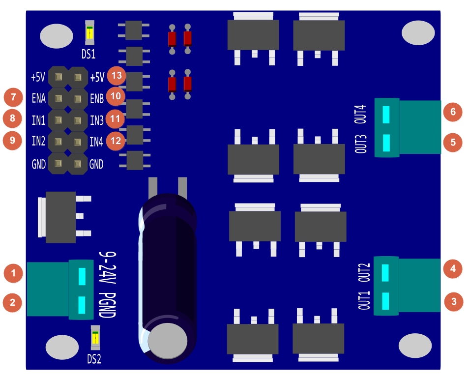
| **Num** | **Label** | - - Description** |
| 1 | 9 - 24V | Power Supply, + |
| 2 | PGND | Power Supply, GND |
| 3 | OUT1 | Motor1_+ |
| 4 | OUT2 | Motor1_- |
| 5 | OUT3 | Motor2_+ |
| 6 | OUT4 | Motor2_- |
| 7 | ENA | Motor1 PWM |
| 8 | IN1 | Motor1 control signal |
| 9 | IN2 | Motor1 control signal |
| 10 | ENB | Motor2 PWM |
| 11 | IN3 | Motor2 control signal |
| 12 | IN4 | Motor2 control signal |
| 13 | +5V | Voltage Reference Input, +5V OR 3.3V |
Control Method
| **IN1** | **IN2** | **ENA/ ENB** | - - Motor1/2 Behavior** |
| 0 | 0 | x | Stop (brake) |
| 1 | 1 | x | Vacant |
| 1 | 0 | 1 | Forward 100% |
| 0 | 1 | 1 | Reverse 100% |
| 1 | 0 | PWM | Forward at PWM speed |
| 0 | 1 | PWM | Reverse at PWM speed |
In this table
- IN1 & IN2: the control signal input to change the motor behavior
- "0": TTL_Low
- "1": TTL_High
- "x": Any TTL, and it is default TTL_Low while no PWM signal.
- "ENA/ ENB": PWM speed setting
 Note:
Note:
-
IN1 & IN2
- To protect your motor, before switching the motor steering direction, make sure firstly to BRAKE motor by setting IN1 - 0 & IN2 - 0, especially when the PWM was set as 100%, full speed. And the suggestion time to brake is >0.1S, depending on your motor.
-
+5V
- When the microcontroller operation voltage is 5V/3.3V, then please connect the reference voltage 5V/ 3.3V from the microcontroller. Or you will fail to control motors.
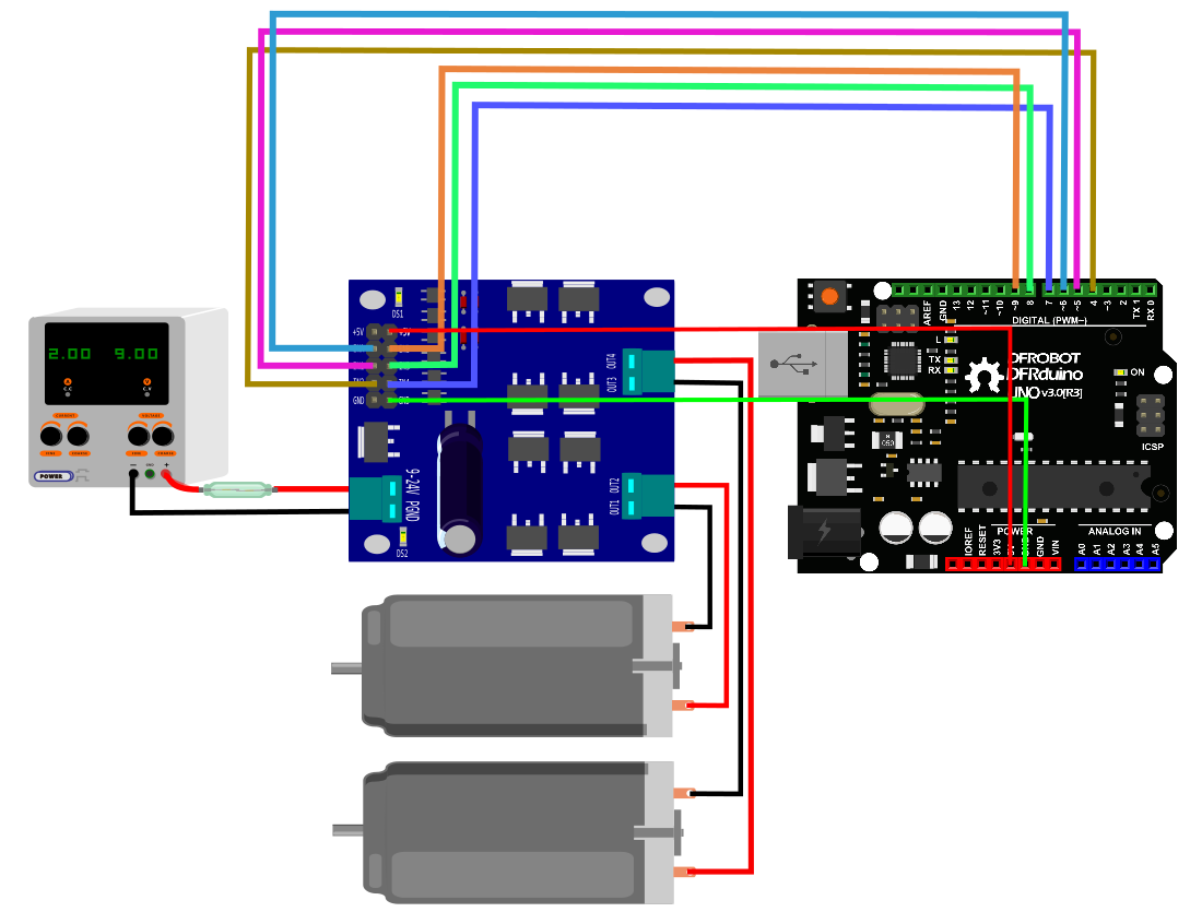
This tutorial will cover how to use PWM to control a motor using the shield. Do the wiring according to the Connection Diagram below, and then upload the sample code below to the Arduino card, here we use a UNO as the controller, you could see your motor run forward for 3 second and then run reversely for another 3 seconds and repeat this behavior then.
-
Hardware
- 1 x DFRduino UNO (or similar)
- 1 x This 7A Dual DC Motor Driver
- 2 x DC Motor
- 1 x Fuse@20A
- Jumper wires
-
Software
- Arduino IDE, [https://www.arduino.cc/en/Main/Software| Click to Download Arduino IDE from Arduino®]
 |
 |
                                           -   **Facility Safety and the Personal Safety:**
                                               -   Please add a fuse@20A between the Power source and this shield.

                                           <!-- -->

                                           -   **Installation Tips**
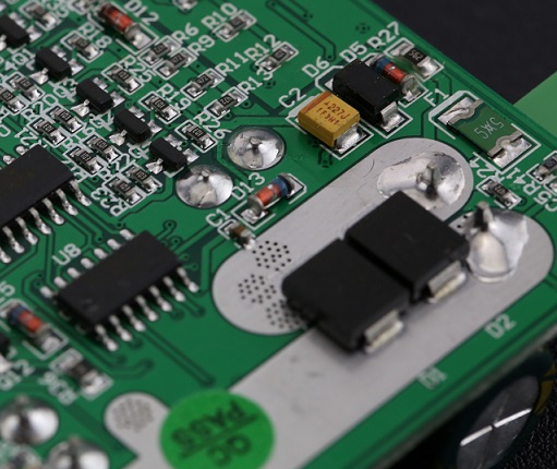
                                               -   The [backside](http://www.dfrobot.com/wiki/images/b/b1/DRI0042_conductive_layer_backside.png) of the driver, as right-hand picture shows, that its conducting layer can be very wide, so you should take some measurements to ensure it won't **short-circuit**, like applying 1mm layer conductive epoxy or any other similar materials.  |
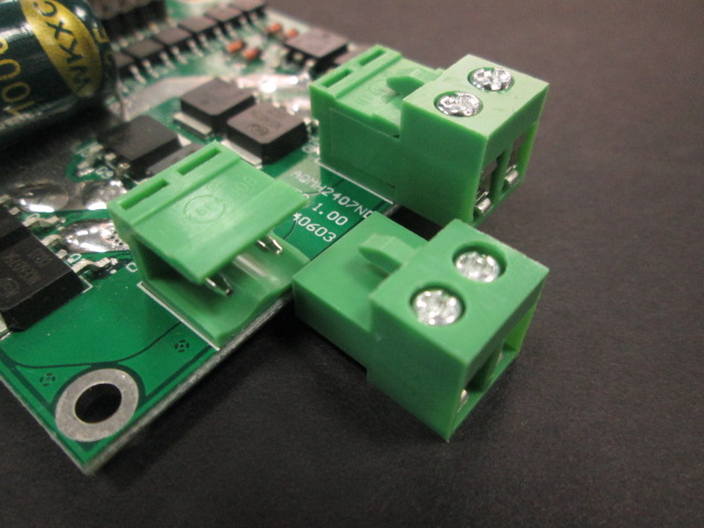
Pluggable Connector
You may find that the connector is designed as pluggable type to adapt with Male or Female wires.
/*
* @file Motor driver DRI0042_Test.ino
* @brief DRI0042_Test.ino  Motor control program
*
* control motor positive inversion
*
* @author [email protected]
* @version  V1.0
* @date  2016-8-10
*/
const int IN1=5;
const int IN2=4;
const int ENA=6;

const int IN3=8;
const int IN4=7;
const int ENB=9;

void setup() {
     pinMode(IN1, OUTPUT);
     pinMode(IN2, OUTPUT);
     pinMode(ENA, OUTPUT);

     pinMode(IN4, OUTPUT);
     pinMode(IN3, OUTPUT);
     pinMode(ENB, OUTPUT);
}

void loop() {
 Motor1_Brake();
 Motor2_Brake();
 delay(100);
 Motor1_Forward(200);
 Motor2_Forward(200);
 delay(1000);
 Motor1_Brake();
 Motor2_Brake();
 delay(100);
 Motor1_Backward(200);
 Motor2_Backward(200);
 delay(1000);
}

void Motor1_Forward(int Speed)
{
     digitalWrite(IN1,HIGH);
     digitalWrite(IN2,LOW);
     analogWrite(ENA,Speed);
}

void Motor1_Backward(int Speed)
{
     digitalWrite(IN1,LOW);
     digitalWrite(IN2,HIGH);
     analogWrite(ENA,Speed);
}
void Motor1_Brake()
{
     digitalWrite(IN1,LOW);
     digitalWrite(IN2,LOW);
}
void Motor2_Forward(int Speed)
{
     digitalWrite(IN3,HIGH);
     digitalWrite(IN4,LOW);
     analogWrite(ENB,Speed);
}

void Motor2_Backward(int Speed)
{
     digitalWrite(IN3,LOW);
     digitalWrite(IN4,HIGH);
     analogWrite(ENB,Speed);
}
void Motor2_Brake()
{
     digitalWrite(IN3,LOW);
     digitalWrite(IN4,LOW);
}| '''Q1. '''General Arduino Problems/FAQ/Tips |
'''A. '''Click the topic link on DFRobot Forum.
 For any questions, advice or cool ideas to share, please visit the DFRobot Forum.
 shopping from dfrobot store or dfrobot distributor.