3 wire_Serial_LCD_Module_(Arduino_Compatible)_(SKU_DFR0091) - jimaobian/DFRobotWiki GitHub Wiki

Introduction
This LCD module uses a 128x64 liquid crystal display that support Chinese character , English characters and even graphics. It can exhibit 4 lines and 12 English characters/6 Chinese characters per line. It is suitable for interactive work with Arduino.
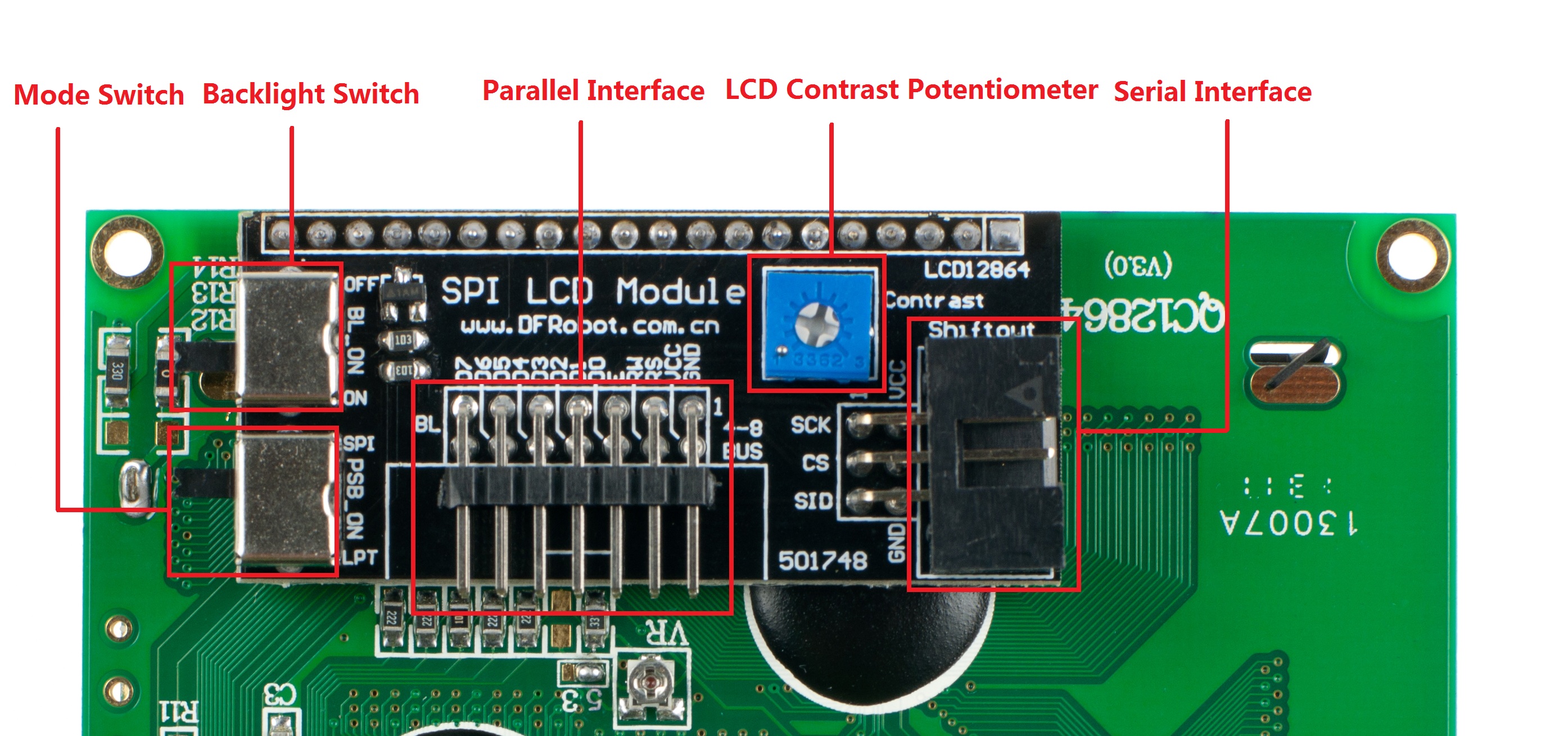
It features a backlit control, pallerlel or serial control, contrast adjust. It can be connect to our interface shield via IDC6 socket and cables. 
Mode Selection
The LCD is shipped in Parallel mode by default. The PSB_ON switch is used to set the interface mode. To switch to 3-Wire mode, Set the switch to SPI.
Code
This sample is working under Parallel mode. You will need Arduino library which can be download here.
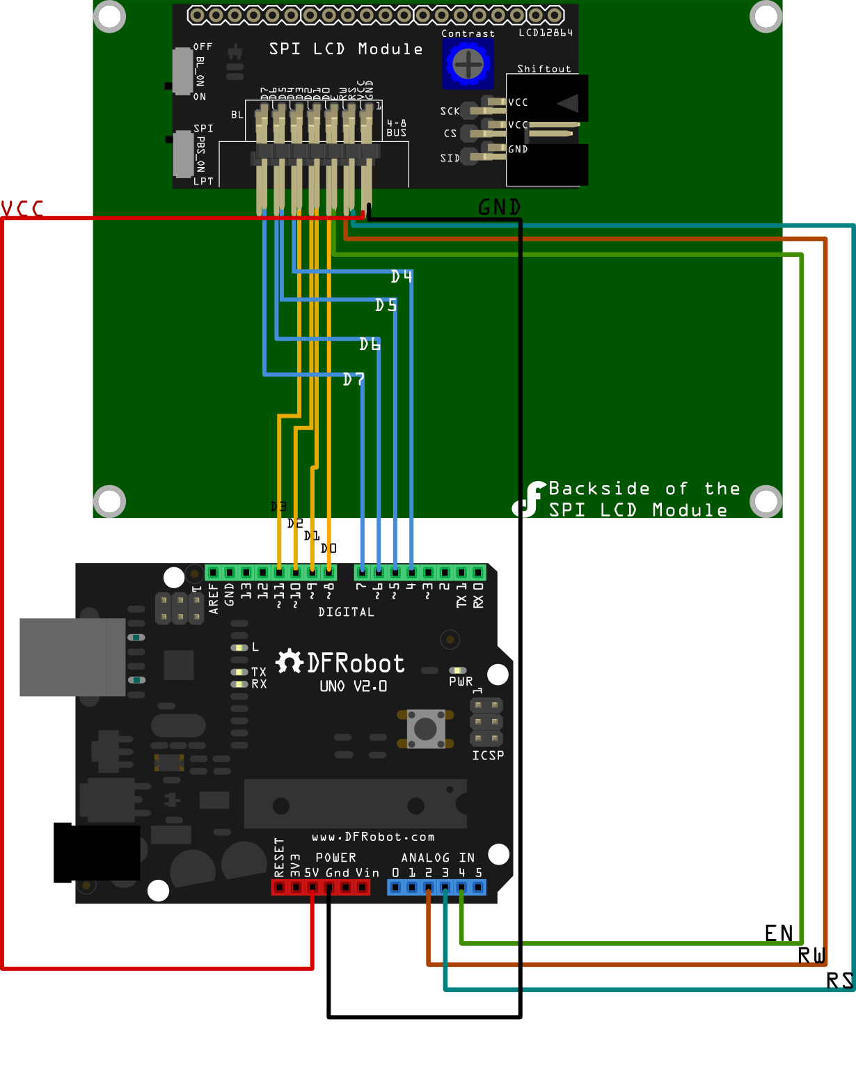
Connection in Parallel mode: 
/*
LCD  Arduino
RS = 17; Analog Pin3
RW = 16; Analog Pin2
EN = 18; Analog Pin4
D0  = 8;
D1  = 9;
D2  = 10;
D3  = 11;
D4  = 4;
D5  = 5;
D6  = 6;
D7  = 7;
PIN15 PSB = 5V;
*/

#include "LCD12864R.h"
#define AR_SIZE( a ) sizeof( a ) / sizeof( a[0] )

unsigned char show0[]={0xBB,0xFA,0xC6,0xF7,0xC8,0xCB,0xC3,0xCE,0xB9,0xA4,0xB3,0xA7};//DFRobot
unsigned char show1[]="www.dfrobot.com";//

void setup()
{
LCDA.Initialise(); // INIT SCREEN
delay(100);
}

void loop()
{
LCDA.CLEAR();//Clear the screen
delay(100);
LCDA.DisplaySig(0,0,0x20);//Display space
delay(100);
LCDA.DisplayString(0,1,show0,AR_SIZE(show0));//LOGO
delay(100);
LCDA.DisplayString(2,0,show1,AR_SIZE(show1));;//LOGO
while(1);
}
The following sample is working under 3-Wire mode. You will need the Arduino Library which can be downloaded here.
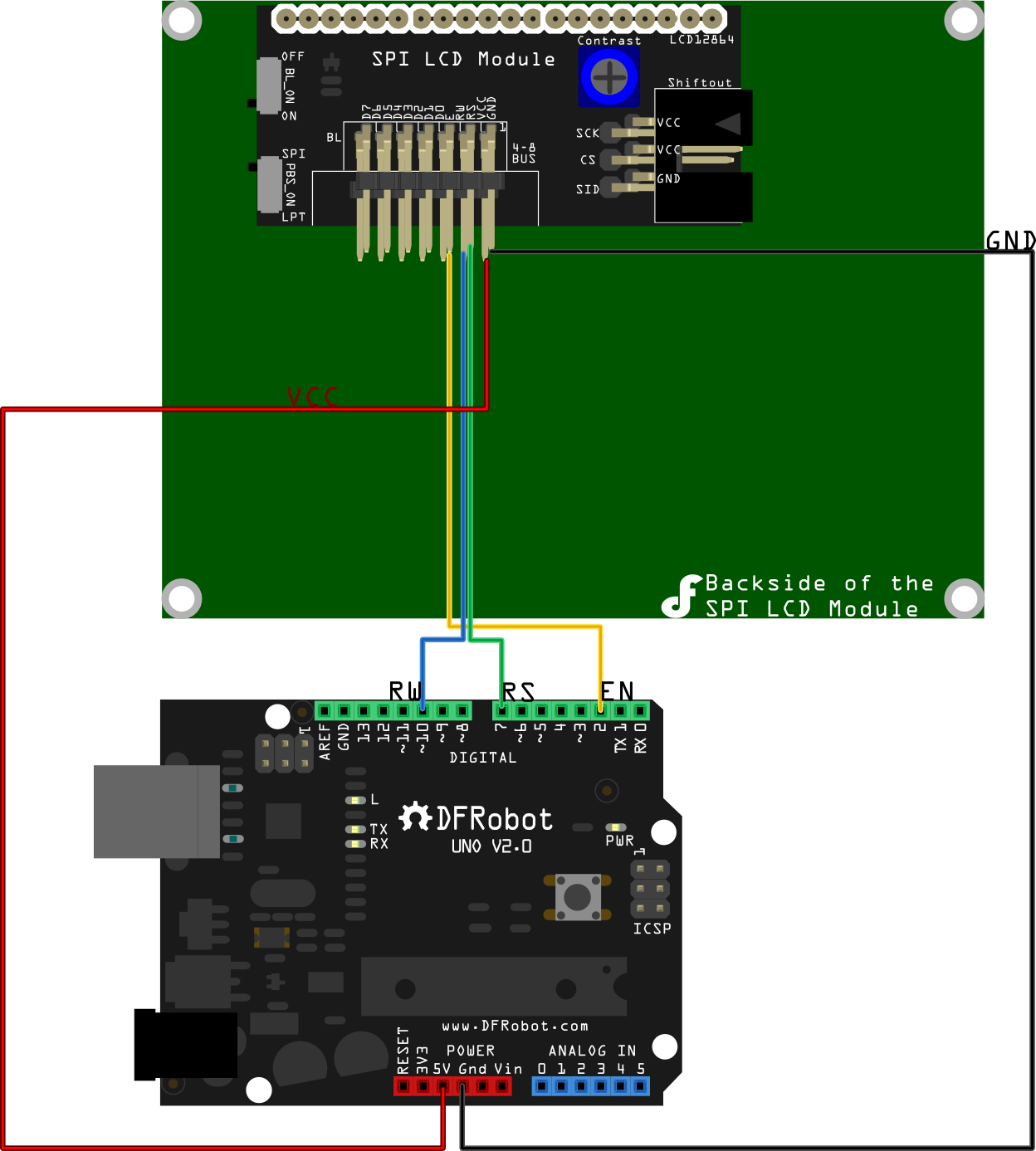
Connection in 3-Wire mode:(2 Methods)
Method1:

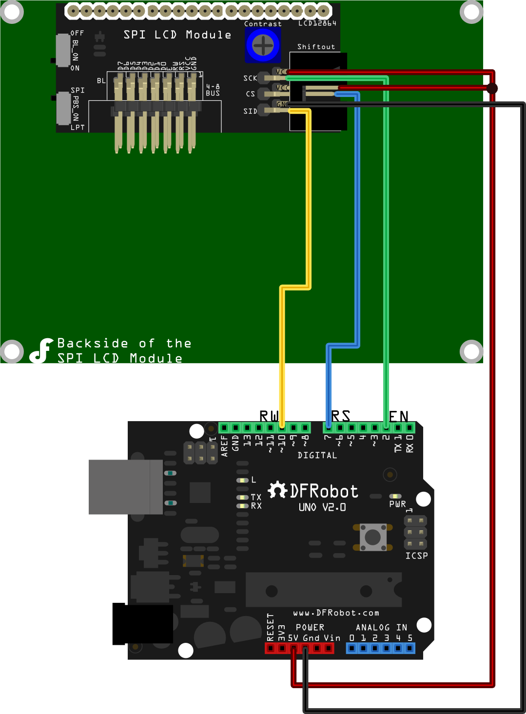
Method2:

/*
1. SPI Interface Inatruction
      clockPin --> SCK(EN)
      latchPin --> CS(RS)
      dataPin --> SID(RW)
 2. Connection:
    1)Turn the BL_ON Switch to the "ON" side;
    2)Turn the PBS_ON Switch to the "SPI" side

Method1:
      LCD                   Arduino
      EN                 Digital Pin 2
      RS                 Digital Pin 7
      RW                 Digital Pin 10
      VCC                     5V
      GND                     GND;

Method2:
      LCD                          Arduino
      SCK       clockPin(defined in the "initDriverPin" function)
      CS        latchPin(defined in the "initDriverPin" function)
      SID       dataPin (defined in the "initDriverPin" function)
      VCC                            5V
      GND                           GND

*/

#include "LCD12864RSPI.h"
#include "DFrobot_bmp.h"
#include "DFrobot_char.h"

#define AR_SIZE( a ) sizeof( a ) / sizeof( a[0] )

unsigned char wangzhi[]=" www.DFRobot.com ";

unsigned char en_char1[]="ST7920 LCD12864 ";

unsigned char en_char2[]="Test, Copyright ";

unsigned char en_char3[]="by DFRobot ---> ";

void setup()
{
  LCDA.initDriverPin(2,7,10);  //INIT SPI Interface
  LCDA.Initialise(); // INIT SCREEN
  delay(100);
  LCDA.DrawFullScreen(logo);//LOGO
  delay(5000);
}

void loop()
{
LCDA.CLEAR();//Clear Screen
delay(100);
LCDA.DisplayString(0,0,en_char1,16);
delay(10);
LCDA.DisplayString(1,0,en_char2,16);
delay(10);
LCDA.DisplayString(2,0,en_char3,16);
delay(10);
LCDA.DisplayString(3,0,wangzhi,16);
delay(5000);
LCDA.CLEAR();//Clear Screen
delay(100);
LCDA.DisplayString(0,0,show1,16);
delay(10);
LCDA.DisplayString(1,0,show2,16);
delay(10);
LCDA.DisplayString(2,0,show3,16);
delay(10);
LCDA.DisplayString(3,0,wangzhi,16);//LOGO
delay(5000);
}
The following sample is working under 3-Wire mode. It demonstrates how to display integers on the LCD scrren. You will need the Arduino Library which can be downloaded here.
/*
1. SPI Interface Inatruction
      clockPin --> SCK(EN)
      latchPin --> CS(RS)
      dataPin --> SID(RW)
 2. Connection:
    1)Turn the BL_ON Switch to the "ON" side;
    2)Turn the PBS_ON Switch to the "SPI" side

Method1:
      LCD                   Arduino
      EN                 Digital Pin 2
      RS                 Digital Pin 7
      RW                 Digital Pin 10
      VCC                     5V
      GND                     GND;

Method2:
      LCD                          Arduino
      SCK       clockPin(defined in the "initDriverPin" function)
      CS        latchPin(defined in the "initDriverPin" function)
      SID       dataPin (defined in the "initDriverPin" function)
      VCC                            5V
      GND                           GND

This sample shows how to use LCD12864 to display integer on the screen, and it uses function itoa() from library stdlib.h
*/

#include "LCD12864RSPI.h"
#include "DFrobot_bmp.h"
#include "DFrobot_char.h"
#include "stdlib.h"
#define AR_SIZE( a ) sizeof( a ) / sizeof( a[0] )

int i=0;  //counter, initial value is 0

unsigned char wangzhi[]=" www.DFRobot.cn ";

unsigned char en_char1[]="ST7920 LCD12864 ";

unsigned char en_char2[]="Test, Copyright ";

unsigned char en_char3[]="by DFRobot ---> ";

void setup()
{
  LCDA.initDriverPin(2,7,10); //INIT SPI Interface
  LCDA.Initialise(); // INIT SCREEN
  delay(100);
  LCDA.DrawFullScreen(logo);//LOGO
  delay(2000);
  randomSeed(0);
  LCDA.CLEAR();
  delay(100);
  LCDA.DisplayString(0,0,en_char1,16);
  delay(10);
  LCDA.DisplayString(1,0,en_char2,16);
  delay(10);
  LCDA.DisplayString(2,0,en_char3,16);
  delay(10);
  LCDA.DisplayString(3,0,wangzhi,16);
  delay(2000);


}

void loop()
{
LCDA.CLEAR();//clear the screen
delay(100);

int number= i; // the interger should be in the range from -32768 ~ 32767
char buf [16];
itoa(number,buf,10); //transform integer into string
unsigned char temp[16];

for (int i=0;i<=15;i++)
{
  if(buf[i]!='0'&&buf[i]!='1'&&buf[i]!='2'&&buf[i]!='3'&&buf[i]!='4'&&buf[i]!='5'&&buf[i]!='6'&&buf[i]!='7'&&buf[i]!='8'&&buf[i]!='9'&&buf[i]!='-')
  {temp[i]=' ';}   // put space into those where no  values are assigned initially
  else
  {temp[i]=buf[i];}
}
LCDA.DisplayString(0,0,temp,16);//display the counter on the screen

delay(1000);
i++; // counter works every 1 second
}
Documents
- Arduino Library(3-Wire)
- Arduiono Library(Parallel)
- The Chinese character is encoded using GBK code. GBK code chart
 shopping 3-wire lcd module (sku:dfr0091)
category: Product Manual category: DFR Series category: LCDs category: source