3 Wire_LED_Module_(SKU_DFR0090) - jimaobian/DFRobotWiki GitHub Wiki

Introduction
This is 8 digital bits serial LED display. It features a flick free display and 3-Wire interface which allows more than 2 modules can be serial linked. With Interface Shield For Arduino (SKU: DFR0074), this module can be plug and play.
Connection
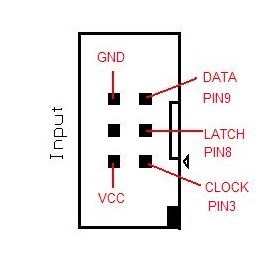
This module is linked to interface shield via IDC6 cables. Make sure that the first input is plugged onto "Input" socket of the module. The "Output" socket is linked to the second module "Input socket".
Pinout Diagram

Sample Code
//Pin connected to latch pin (ST_CP) of 74HC595
const int latchPin = 8;
//Pin connected to clock pin (SH_CP) of 74HC595
const int clockPin = 3;
////Pin connected to Data in (DS) of 74HC595
const int dataPin = 9;
byte Tab[]={0xc0,0xf9,0xa4,0xb0,0x99,0x92,0x82,0xf8,0x80,0x90,0xff};
void setup() {
  //set pins to output because they are addressed in the main loop
  pinMode(latchPin, OUTPUT);
  pinMode(dataPin, OUTPUT);
  pinMode(clockPin, OUTPUT);
  Serial.begin(9600);
  Serial.println("reset");
}
void loop() {
  if (Serial.available() > 0) {
    // ASCII '0' through '9' characters are
    // represented by the values 48 through 57.
    // so if the user types a number from 0 through 9 in ASCII,
    // you can subtract 48 to get the actual value:
  int bitToSet = Serial.read() - 48;
  // write to the shift register with the correct bit set high:
  digitalWrite(latchPin, LOW);
  // shift the bits out:
  shiftOut(dataPin, clockPin, MSBFIRST, Tab[bitToSet]);
    // turn on the output so the LEDs can light up:
  digitalWrite(latchPin, HIGH);
  }
}
Additional sample code with the capability to print letters.
//Pin connected to latch pin (ST_CP) of 74HC595
const int latchPin = 8;
//Pin connected to clock pin (SH_CP) of 74HC595
const int clockPin = 3;
////Pin connected to Data in (DS) of 74HC595
const int dataPin = 9;

byte Tab[]={0xc0,0xf9,0xa4,0xb0,0x99,0x92,0x82,0xf8,0x80,0x90,0xff}; //0,1,2,3,4,5,6,7,8,9, ALL OFF
byte Taf[]={0xA0,0x83,0xa7,0xa1,0x86,0x8e,0xc2,0x8b,0xe6,0xe1,0x89,0xc7,0xaa,0xc8,0xa3,0x8c,0x98,0xce,0x9b
,0x87,0xc1,0xe3,0xd5,0xb6,0x91,0xb8};//a,b,c,d,e,f,g,h,i,j,k,l,o,m,n,o,p,q,r,s,t,u,v,w,x,y,z
byte Tap[]={0xff,0x7f}; //"space", "."


void setup() {
  //set pins to output because they are addressed in the main loop
  pinMode(latchPin, OUTPUT);
  pinMode(dataPin, OUTPUT);
  pinMode(clockPin, OUTPUT);
  Serial.begin(9600);
  Serial.println("reset");
}
void loop() {
  if (Serial.available() > 0) {

  int bitToSet = Serial.read();
  //test for "space"
  if (bitToSet == 32){
    digitalWrite(latchPin, LOW);
    shiftOut(dataPin, clockPin, MSBFIRST, Tap[0]);
    digitalWrite(latchPin, HIGH);
  }
  //test for "."
   else if (bitToSet == 46){
    digitalWrite(latchPin, LOW);
    shiftOut(dataPin, clockPin, MSBFIRST, Tap[1]);
    digitalWrite(latchPin, HIGH);
   }

   //test for numbers
   else if (bitToSet <= 57){
    bitToSet= bitToSet - 48;
    digitalWrite(latchPin, LOW);
    shiftOut(dataPin, clockPin, MSBFIRST, Tab[bitToSet]);
    digitalWrite(latchPin, HIGH);
  }
  //test for letters
  else {
    bitToSet= bitToSet - 97;
    digitalWrite(latchPin, LOW);
    shiftOut(dataPin, clockPin, MSBFIRST, Taf[bitToSet]);
    digitalWrite(latchPin, HIGH);
  }

  // write to the shift register with the correct bit set high:
  //digitalWrite(latchPin, LOW);
  // shift the bits out:
 // shiftOut(dataPin, clockPin, MSBFIRST, Tab[bitToSet]);
    // turn on the output so the LEDs can light up:
 // digitalWrite(latchPin, HIGH);
  }
}
Test Procedure
- Upload the sketch above.
- Link "Input" socket for LED Module to "shiftout" socket of interface shield
- Open serial monitor, and type "12345678". The LED module should display "87654321"
Operating procedure
The Arrays Tab and Taf contain numbers and letters encoded as HEX which tells the LED Module which segments to light.
For example the first element of Tab =0xC0 which is the number 0.
 0=0xC0
 0xC0=11000000
The zeros and ones represent the light(0's) segments and the off(1's) segments from the 7 segment display.
P G F E D C B A

  A
  --
F|__|B
E|G |C
  --   .P
  D
So in this case P and G will be off. which makes 0
If you want to make your own letters here are some more resources to explain:
Seven Segment display Wiki Pattern tables Ascii tables are used to see the equivalence. You can see on this table:
DEC CHR
48  0 //This is why we subtract 48 for the first element in the number array
97  a //This is why we subtract 97 for the first element in the alphabet array
 shopping 3-wire led module (sku:dfr0090)
category: Product Manual category: DFR Series