FPGA Broadcast Firmware - jhu-cisst/mechatronics-firmware GitHub Wiki
About
Starting with Rev 4, the firmware supports using asynchronous broadcast to reduce general I/O time. At JHU, this enables us to run a four arm da Vinci system at 6 kHz.
There are three supported protocols:
- PROTOCOL_SEQ_RW: sequential (individual) read and write to each board
- PROTOCOL_SEQ_R_BC_W: sequential read from each board, broadcast write to all boards
- PROTOCOL_BC_QRW: broadcast query, read, and write to/from all boards
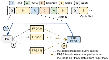
The Amp1394 software will use PROTOCOL_SEQ_RW if any connected FPGA board has firmware Rev 3 or below. It will use PROTOCOL_SEQ_R_BC_W (broadcast writes) if all connected FPGA boards have firmware Rev 4 or higher. With firmware Rev 4 or higher, it is also possible to use PROTOCOL_BC_QRW, where the PC sends a "query" broadcast message which causes all FPGA boards to send their feedback information; this feedback is cached on all FPGA boards, so the PC can then read all feedback from a single board (this board is called the Hub). This protocol is not the default due to some reported hardware issues described below, but can be enabled via software.
NOTE: Different versions of firmware introduced substantial changes to the broadcast protocols (PROTOCOL_SEQ_R_BC_W and PROTOCOL_BC_QRW) and thus those protocols can only be used when all boards are compatible, as in the following cases:
- All boards are Rev 4-6
- All boards are Rev 7
- All boards are Rev 8-9
NOTE: Some FireWire cards have been reported (http://tinyurl.com/mwhq8ap) to have implementation issues and may drop packets, e.g. Ricoh R5C832 card used on Lenovo T530. Note, if you have this issue, very likely you cannot verify the firmware using pgm1394.
Broadcast Protocol
 The protocol contains the following major steps
- PC sends special broadcast quadlet write packet to trigger broadcast read.
- Each FPGA broadcasts its status out
- On FireWire, this is sequential based on node id (TDMA like)
- On Ethernet, raw multicast frames are sent and arbitration is handled by the FIFOs in the embedded Ethernet switches
- Each FPGA caches status locally
- PC reads from a single FPGA board (the Hub board) to obtain cached data from all boards
- On FireWire, any board can be the Hub
- On Ethernet, the board with the shortest number of hops to the PC is the Hub
- On Ethernet/FireWire bridge, the board directly connected to the PC is the Hub
- PC does control computation
- PC broadcasts (or multicasts) write commands
- FPGA extracts command data targeted at it
Packet Format
Broadcast Packet from PC
Packet format
| dest_id = 0xFFFF | tl  |rt| tcode| pri |     tcode = 0x1  pri != 0xA
| src_id = Node_pc |     0xFFFF          |
|     0xFF00 0000                        |
|    data_len      |  ext_code = 0x0000  |
|             header_CRC                 |
|             data block                 |
|               ......                   |
|           last data block              |
|              data CRC                  |
NOTE:
- Packet type: block write request
- dest addr = 0xFFFF FF00 0000
- data in broadcast mode need to set bit 27-24 to be targeted board's board ID, note this is different from regular packet
- Link: Interface Specification
Broadcast Packet from FPGA
Packet format (Firmware Rev 4-7)
| dest_id = 0xFFFF | tl  |rt| tcode| pri |     tcode = 0x1  pri = 0xA
| src_id = Node_pc |     0xFFFF          |
|     0xFFX0 0000                        |     X is the FPGA bid (rotary switch) -- not sure this is correct (see below)
|    data_len      |  ext_code = 0x0000  |
|             header_CRC                 |
|      seq no.     |  board exist flag   |
|             data block                 |
|               ......                   |
|           last data block              |
|              data CRC                  |
Packet format (Firmware Rev 8)
| dest_id = 0xFFFF | tl  |rt| tcode| pri |     tcode = 0x1  pri = 0xA
| src_id = Node_pc |     0xFFFF          |
|     0xFF00 1000                        |
|    data_len      |  ext_code = 0x0000  |
|             header_CRC                 |
|      seq no.     |  block size (quads) |
|             data block                 |
|               ......                   |
|           last data block              |
|              data CRC                  |
NOTE:
- Pri must be set to 0xA. Pri is not used in cable environment in usual application and is reused here to distinguish between block broadcast packet from PC or FPGA node. [Not sure if this is still needed]
- Firmware Rev 4-7, dest addr = 0xFFFF FFX0 0000, X should be set as FPGA bid ID [This may not be correct, code seems to use 0xFFFF FF00 1xX0, where xX is the board id in bits 5-8]
- a sequence number is included for safety check
- data block format is same as block read response, see Interface Specification
Hub Memory Format
Hub memory is allocated as a 2048 bytes memory block with 9-bit address bits (512 x 32 bits, where each entry is a 32-bit quadlet). For firmware prior to Rev 8, four address bits [8:5] specify the FPGA board ID. Thus, each FPGA needs to broadcast its status data block to its reserved address. Starting with Rev 8, the status data blocks are stored contiguously in the memory, rather than to a reserved address range. See HubReg.v
Firmware Rev 7+ modified the block read from Hub memory to become a contiguous read of quadlets. For example, if boards 0, 4, and 9 are the only boards connected in a system, the host PC should perform a block read of 87 quadlets (3 boards x 29 quadlets/board) to obtain the data from those boards. With previous versions of firmware, it would have been necessary to read data from at least 10 boards (to get the data for boards 0, 4 and 9). Also, with Firmware Rev 7+, reading an extra quadlet (e.g., 88 quadlets in the above example) will return timing information in the last quadlet.
Notes for Programming
- Hub node is automatically set as the last board added to the board list (for FireWire). For Ethernet/FireWire, the Hub node is the board that is connected to the PC via Ethernet. For Ethernet-only, the system automatically sets the Hub node based on which participating board has the shortest path to the PC.
- For Ethernet-only, the Hub node sends an unsolicitated read packet, containing data from all boards, to the host PC. For FireWire and Ethernet/FireWire, the host PC must issue an asynchronous read command.
- Use ReadAllBoardsBroadcast & WriteAllBoardsBroadcast instead of ReadAllBoards & WriteAllBoards. Note that the ReadAllBoards and WriteAllBoards will call the corresponding broadcast version if a broadcast protocol is being used.