Ethernet Interface - jhu-cisst/mechatronics-firmware GitHub Wiki
About
This page documents the design of the Ethernet interface. In a nutshell, complete FireWire packets (including header and checksum) are packaged in either raw Ethernet frames or in UDP packets. Thus, when the FPGA board receives the packet via Ethernet, minimal effort is required to forward that packet to other nodes (if necessary) via the FireWire bus.
The Ethernet interface was previously called Eth1394, but that has been dropped to avoid confusion with an earlier eth1394 protocol for IP over FireWire, which was later superseded by RFC2734. We are doing the opposite, which is to send FireWire packets over Ethernet (i.e., within an Ethernet IP frame).
Motivation
The motivation for creating an Ethernet interface includes:
- Ethernet connectors are more prevalent in modern computers
- The FireWire interface relies on
libraw1394, which is only available on Linux - The Ethernet interface would be compatible with other platforms, such as Simulink Real-Time (previously called Matlab xPC)
- Modern real-time Linux kernels (e.g., Xenomai) support a real-time Ethernet driver (RTnet), but not a real-time FireWire driver
System Setup
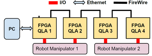
The following figure depicts the use of the Ethernet interface between the Control PC and the FPGA nodes on the FireWire bus. In this configuration, FPGA/QLA 1 would act as the Ethernet/FireWire bridge (it would also act as the "hub" node for broadcast transfers).
Verilog Source Code
The Ethernet interface is provided in the file EthernetIO.v and in the relevant link-layer (PHY) file, which is KSZ8851.v for FPGA V2 and VirtualPhy.v for FPGA V3. Note that FPGA V3 uses a virtual PHY because it is connected to an internal 4-port Ethernet switch, rather than to either of the two physical RTL8211F PHYs.
FireWire Changes
The FireWire.v implements the IEEE-1394 (FireWire) interface. The initial implementation assumed that the FPGA board would be a peripheral node, reacting to frames received (primarily from the control PC). With the Ethernet interface, however, the FireWire module is called to perform a given task (according to the FSM). We can do this because the bridge acts as a "commander" for other nodes on the FireWire bus. Thus, for the Ethernet board, the FireWire module had to be modified to add the following capabilities, which would normally be performed by the control PC:
- transmit PC request
- transmit broadcast read (BC) request
- receive ACK for PC request
- receive ACK for BC request
- receive response for PC request
- receive response for BC request
The completion of each task is indicated by a specific trigger, which will drive the finite state machine (FSM) in the top module.
Ethernet Packets
The implementation uses valid MAC addresses; specifically, it uses the PC MAC address for the PC, and the following MAC address for the FPGA: FA:61:0E:13:94:0n, where n is the FPGA board number (0-F). Note that the MAC address is based on the Company ID (CID) obtained for LCSR from IEEE, which is FA:61:0E.
See here for details about the Ethernet packets.
Publications
The design of the Ethernet/FireWire bridge is described in the following paper. However, note that one significant change is that this paper describes the use of a dedicated FPGA board to serve as the Ethernet/FireWire bridge, whereas the current design allows any FPGA board in the system to act as the bridge (i.e., the board can also be coupled with a QLA and provide full functionality). Also, this paper used raw Ethernet frames rather than UDP.
L. Qian, Z. Chen, P. Kazanzides, "An Ethernet to FireWire bridge for real-time control of the da Vinci Research Kit (dVRK)”, IEEE Conf. on Emerging Technologies and Factory Automation (ETFA), Luxembourg, Sept. 2015.