3.6 Serial Troubleshooting - jgyates/genmon GitHub Wiki
Serial Troubleshooting
If you have followed the directions on this page and are experiencing problems, this document is a guide for troubleshooting serial issues.
NOTE: If you are running Raspberry Pi OS 12 (Bookworm) or higher or running in a managed python environment you will need to activate the virtual python environment before running the serial test described below. This page describes how to enabled and disable the virtual python environment.
NOTE: If you are using a Generac 4.5L Liquid Cooled Engine please see the Known Issues Wiki entry regarding changing the genmon data rate for this specific controller. If you are using this model generator genmon will not work until you change the data rate.
Make Sure You Have the Correct Hardware
The RS-232 converter board needs to support 3.3Vs and the board should be powered from the 3.3V (pin 1 on the Pi connector) supply on the Raspberry Pi.
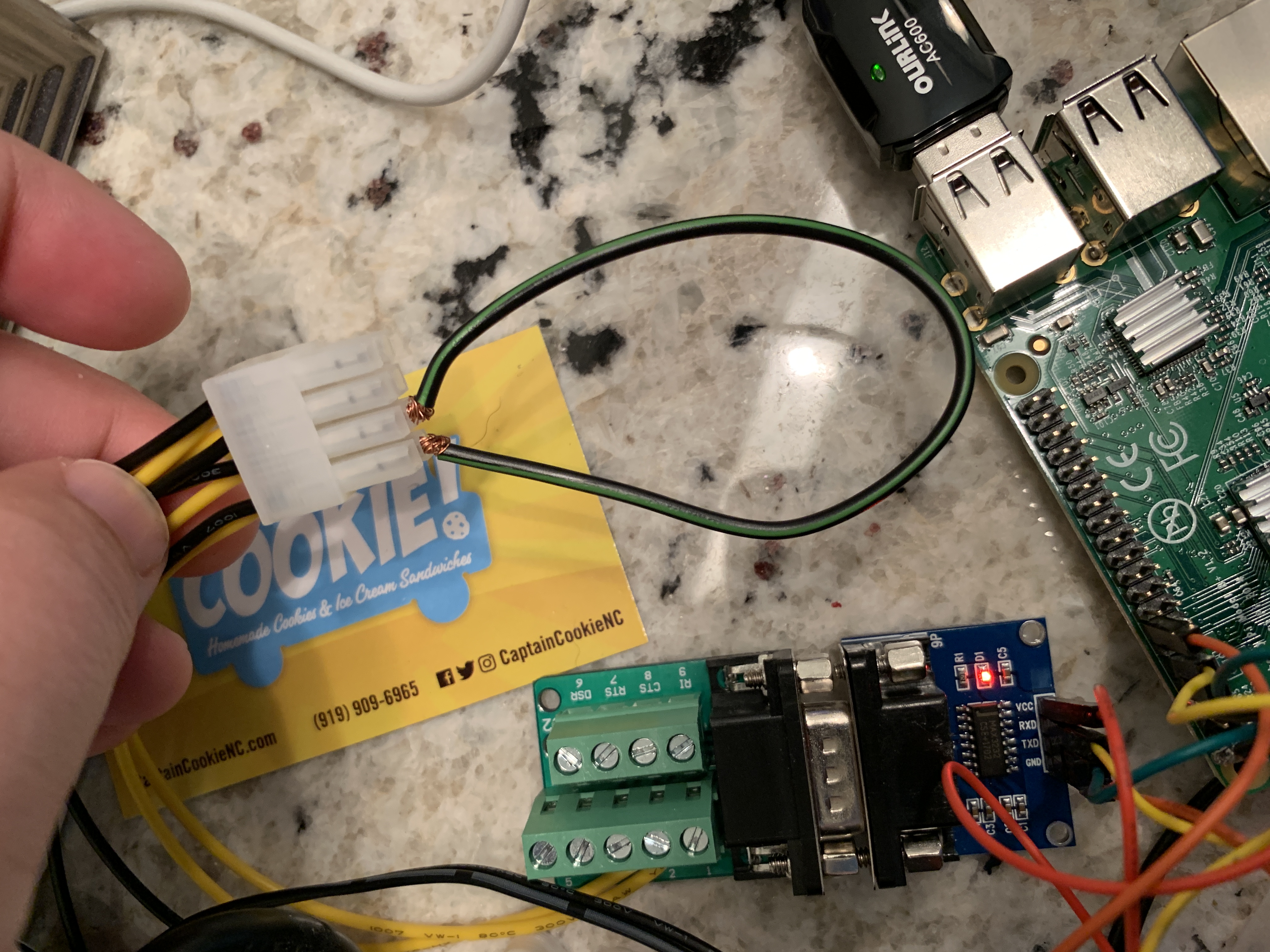
Make Sure You Have the Pi Properly Grounded
The controller and the pi need to have a common ground. You can achieve this by getting power and ground the pi to the battery via a 12V to USB converter or you can power from another source (Controller Molex connector, Power over Ethernet, etc.). If you power from a source other than the battery you will need to connect a ground wire from the molex connector on the controller to the RS-232 9-pin connector. If loopback test below pass and you have validated the the Tx and Rx are correctly wired to the controller molex cable, then you could have a bad ground connections. Bad ground connections will cause serial errors or even a lack of communication on the serial link. To validate your ground has a good connection, use a multi-meter to measure continuity between the generator battery negative terminal and the ground on the the pi. If your meter does not show continuity then this will cause serial errors or lack of data. To be on the safe side, always connect the ground on the molex connector to your RS-232 ground.
Verify Your Pi Serial Sort is Setup Correctly
The setup guide details the steps needed to setup your pi. To validate this setup you can use the program serialconfig.py. This program is located in the /OtherApps directory in the project repository and it will validate your settings are correct. If you installed the 64 bit version of the operating system on your Pi you can validate the Raspberry Pi GPIO pins are setup for serial communications with the pinctrl utility. The following command:
pinctrl get 14,15
will output this with a correctly configured Pi:
 14: a4    pn | hi // PIN8/GPIO14 = TXD0
 15: a4    pu | hi // PIN10/GPIO15 = RXD0
The above shows that GPIO 14 is set for Transmit (TXD0) UART0 and GPIO 15 is set for Receive (RXD0) on UART0.
Validate Your Connections
One of the most common types of mistakes in setting up the project is mis-wiring the molex connector. One way to validate your connections are going to the correct pin is to use a multimeter and check that pin 1 on the molex connect has 5 volts and pin 2 is ground. If you can validate these connections you can at minimum set a base line that you have the orientation of the connector correct. The loopback test below can further validate the Tx and Rx pins are correct.
Run a Loopback Test
There are three types of loopback tests you can run. Each of the tests use the program serialtest.py provided in the project repository. When running serialtest.py you must make sure that genmon.py is not running. To stop genmon.py you you can type:
bash ./startgenmon.sh stop
The three types of loopback tests are:
Loopback at the Pi Expansion Connector This test assumes you are using the internal Pi serial port. Loopback pin 8 (transmit) and pin 10 (receive) at the pi expansion connector. With your RS232 board disconnected from the PI GPIO pins, connect both pin 8 and pin 10 on the PI GPIO board together using a jumper wire/dupont cable. Connecting these pins and running serialtest.py will validate that the serial port has been correctly configured on your Pi and that you are ready to connect your RS232 board. The program can be executed with no additional parameters if you are using the built in serial port on the pi and it has been assigned to /dev/serial0. From the OtherApps directory type:
python3 serialtest.py
If this test passes then you have your pi setup correctly. Then proceed to the next test.
If it fails or passes intermittently, check your connections, power and ground for the pi and validate you have the settings in /boot/cmdline.txt and /boot/config.txt correct if you are using the build in serial port. A common issue if this test fails is skipping a step on the setup. Use serialconfig.py to validate this.
Loopback at the serial 9 Pin Connector This test will loopback pins 2 to 3 on the 9 pin serial connector. You must have the RS-232 converter board correctly wired to the Pi expansion header to run this test if you are using the internal serial port. If you are using the internal port you can type:
python3 serialtest.py
If you are using a USB serial port you can use the device name as a command line parameter:
python3 serialtest.py /dev/ttyUSB0
If this test fails and you are using a USB serial port, you may want to consider checking your syslog for USB disconnect events. USB devices can become disconnected or cycle power if the pi can not supply enough power to the USB device.
If this test fails and your are using the internal serial port, but the first loopback test passes (looping pin 8 to 10 at the expansion connector) then you likely have your RS-232 converter board wired incorrectly. May of the RS-232 converter boards have LEDs that indicate power and Transmit or Receive traffic so take note if your converter board does as this can aid in determining the source of your problem. The converter board has two interfaces, one connects to the pi and the other has a 9-pin connector that has RS-232 transmit, receive and ground signals. The side that connects to the Pi must have VCC (power) connected to Pin 1 on the pi (3.3V) and ground on the converter board connected to one of the ground pins on the pi expansion header (e.g. pin 6).
Loopback at the Far End of Your Cable This test will test the communications path from the pi, through your RS-232 converter board and through your cable. To perform this test loopback the transmit and receive pins on the molex connector (pings 7 and 8).
If this test fails and the first two test pass the you have an issue with your cable.
If this test passes but you still can not receive data with the Generator Monitor, then try swapping your transmit and receive connections in your cable (not the converter board). Note: the diagram for the cable in the repository has wiring for both a DTE and DCE serial connector. The wiring is different for a DTE vs a DCE connector. Another thing that could be wrong if you fail this test is a bad connection in your molex connector.
If you have timeout errors in /var/log/mymodbus.log but no serial errors in /var/log/myserial.log when running genmon.py then you may have a bad connection on the transmit line of your cable.
Other Issues
If you tests pass but your are seeing communications errors or not communication, check the log file /var/log/myserial.log or /var/log/mymodbus.log for errors related to serial communications and modbus traffic. If you see this message in your /var/log/myserial.log:
device reports readiness to read but returned no data
it could mean that another program is using the serial port. Check for multiple copies of the software running (it is best to always use the "bash ./startgenmon.sh restart" instead of the "start" and "stop" commands) or check for another program using the serial port. If you are using a USB device, this error could mean that you device is disconnecting, likely due to power issues or a bad USB design. If this is the case, try powering your pi from a better source, replacing your USB serial device, or use a powered USB hub. The following command can provide some insight into pi power issues.
vcgencmd get_throttled
This command will output a hexadecimal number in this format:
Bit: Meaning
0: under-voltage (0xX0001)
1: arm frequency capped (0xX0002 or 0xX0003 with under-voltage)
2: currently throttled (0xX0004 or 0xX0005 with under-voltage)
16: under-voltage has occurred (0x1000X)
17: arm frequency capped has occurred (0x2000X or 0x3000X also under-voltage occurred)
18: throttling has occurred (0x4000X or 0x5000X also under-voltage occurred)
If you are experiencing USB disconnects and get_throttled shows under-voltage has occurred your USB device may be drawing too much power for the pi to provide. If you are seeing USB disconnects with no issues shows by get_throttled your USB device may be poorly designed or defective.