3.1 Making a Cable - jgyates/genmon GitHub Wiki
Creating a Cable
To make a cable to connect your raspberry pi to your generator controller you will need a raspberry pi, a TTL to RS-232 level converter to change the serial port signals from the Pi from 3.3V to RS-232 voltage levels, wire, a molex connector, at least 2 molex pins and a crimping tool. The Hardware Wiki Page includes part numbers all of these items. If you are new to using crimp tools to create cable connectors, I would suggest YouTube as a resource. There are many "How To" videos that should help with any learning curve. I searched on "Molex Crimping Tool" and found a few.
This is a video on how to Crimp Molex Connectors
An highly recommended alternative, and possibly easier method for creating a cable is to purchase the following two items and splice them together. This does not require crimping a custom molex connector:
- Cable Connector for interfacing to generator. Available at amazon or ebay.com
- Interface for DB-9 serial
Depending on the length of cable you need you may need to buy multiple cable connector and connect them together.
Another thing to consider when making a cable: Make sure your connections to the molex are secure. Depending on your generator and the mounting of your equipment, vibrations could cause loose molex pins to introduce serial data errors that are only appear when the generator is running.
RS-232 Pinout
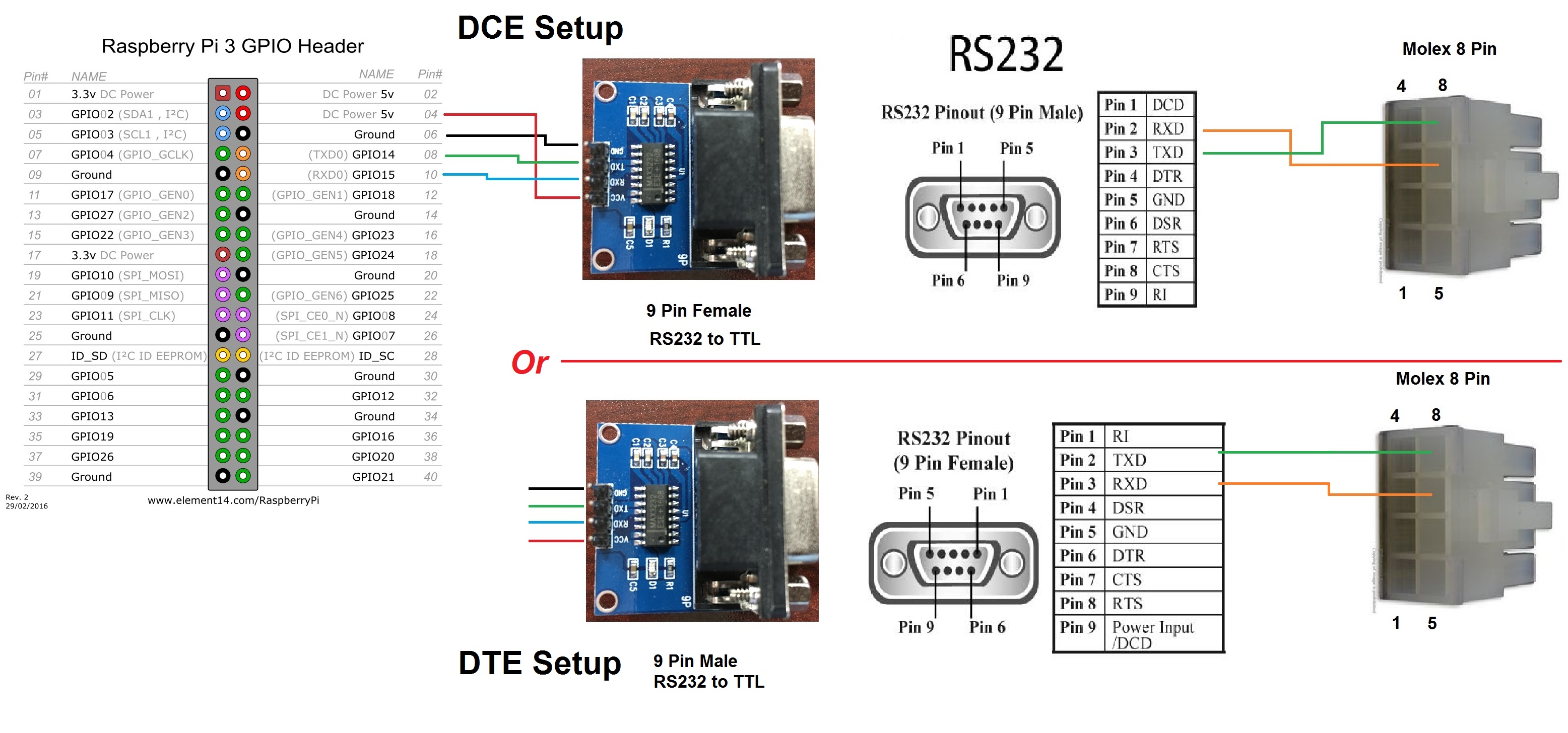
Depending on the type of TTL to RS-232 converter you use, your converter may have a male or female DB-9 connector. If you use a male connector this is typically a DTE interface and pin 2 is receive (input) and pin 3 is transmit (output). A female interface is typically a DCE interface and pin 3 is receive (input) and pin 2 is transmit (output). In most wiring diagrams the DTE connections will list the actual name of the signal (e.g. Tx or Rx) and DCE interfaces will list what you should connect to the far end. This allows DTE and DCE connections to be directly connected via a straight cable. Since we are connecting to a molex connector with a custom cable you must be aware of the type of connector you use. The following links describe the differences between DTE and DCE connectors:
Differences between DTE and DCE
NOTE A DCE connector will generally be labeled as the expected connection from the end it is connected to (i.e. Transmit is an input). This leads to confusion on the connection of transmit and receive. This page has a good picture of the differences between DCE and DTE connectors.
All diagrams shown are available in the Diagrams folder in the project repository.
Wiring Diagram with Female (DCE) or Male (DTE) connector:
Molex Female Pinout (Digikey P/N WM3703-ND):
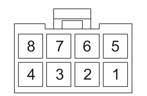 NOTE: The above diagram is of the controller receptacle, not the mating plug
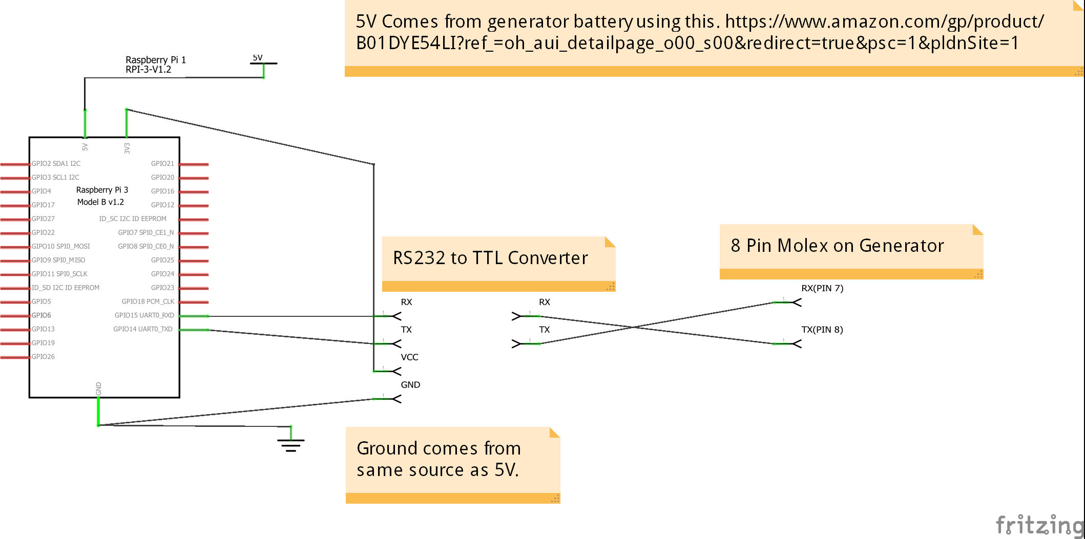
Schematic:
Evolution 1.0 and Nexus Aux Port Pinout:
Pin 8  - Transmit from Controller, connect to Receive on the Pi
Pin 7  - Received to the Controller, connect to Transmit on the Pi
Pin 2  - Ground.
Pin 1  - 5V. This is an optional method for powering your Pi, however this does not supply enough power for newer pi models like the Pi3 or Pi4
The Evolution 2.0 Controller Aux Port Pinout adds these to the above pinout:
Pin 3 - +12V Accessory Power
Pin 4 - RS-232 port ground (there have been some instances that pin 4 did not work as as suitable ground, if pin 4 does not allow reliable serial communications pin 2 should work for Evolution 2, Evolution 1 and Nexus)
Pin 5 - RS-485 Data (-), Used for built in WiFi support
Pin 6 - RS-485 Data (+), Used for built in WiFi support
Unless you Pi power supply ground is common to the generator battery ground you will need to connect ground to your serial ground on your Pi.
NOTE: Some people have reported undervoltage errors on the Pi 3 (not the Pi Zero) when powering through the controller connector. While this has not been reported to prevent the application from running it may not be an ideal way to power the Pi. See this issue for more details.
NOTE: If you RS-232 converter is powered using 5V the output of the receive lines to the PI are also 5V, according to the MAX3232 data sheet. The ideal solution would be to power your converter from the 3.3V pin on the GPIO header. I have yet to see a situation when powering your converter from the 5V supply did not work or damaged a pi, however the information on the PI and the MAX3232 chip does to point to the 3.3V supply being the ideal solution.
NOTE: If you have an Evolution 2.0 unit with the wifi module you have a few choices:
- Do not use the wifi module (unplug it) and directly connect the pi to the molex connector. This option will not allow your firmware to automatically updated via wifi. This may or may not be desired depending on your perspective. Updating your firmware in the future could prevent genmon from working if future versions of the firmware include features designed to prohibit genmon from working.
- Use the wifi module with genmon by re-pinning the connector since the wifi module uses separate pins on the molex connector than the pi uses. Care should be taken if you attempt to modify the existing molex connector on the wifi module as any mistakes could damage your connector. This thread has more discussion on the topic.
Note that depending on your generator model and your controller type, the position of the molex connector on the back of your generator will vary. The following is a picture of the connector. It will be an eight pin connector and it may have a sticker over it. There are a separate models of the Nexus and Evolution Controllers for liquid cooled and air cooled generators and the placement of the connector is different for each model. The connector should be the only eight pin connector on the back of your generator controller.
The length of your cable is also specific to your generator model and type.
Controller Connection:
.jpg)