The bootstrap capacitor - jean-michel-gonet/rc-to-dc-motor-controller GitHub Wiki
Bootstrap capacitor is a technique to bring enough voltage to the gate of a MOSFET-N high side of a bridge so it opens.
The problem to solve:
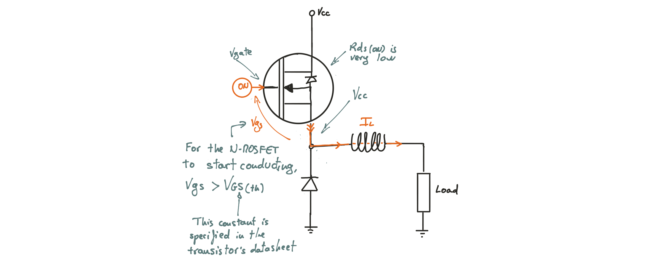
Let’s take a Buck converter as running example. This is a near-ideal circuit based on a N channel MOSFET:

MOSFET transistors are commonly used as a switch because when they’re on their resistance, Rds(on), is very low. And, among those, the N channel MOFET are preferred over P channel because they are cheaper, stronger and can lead more current.
The catch is that, for a N channel MOSFET to open, the gate has to be at a higher voltage than the source. But source voltage is very close to power voltage because, when turned on, a MOSFET has very little resistance between drain and source. As a consequence, the gate voltage has to be above power voltage.

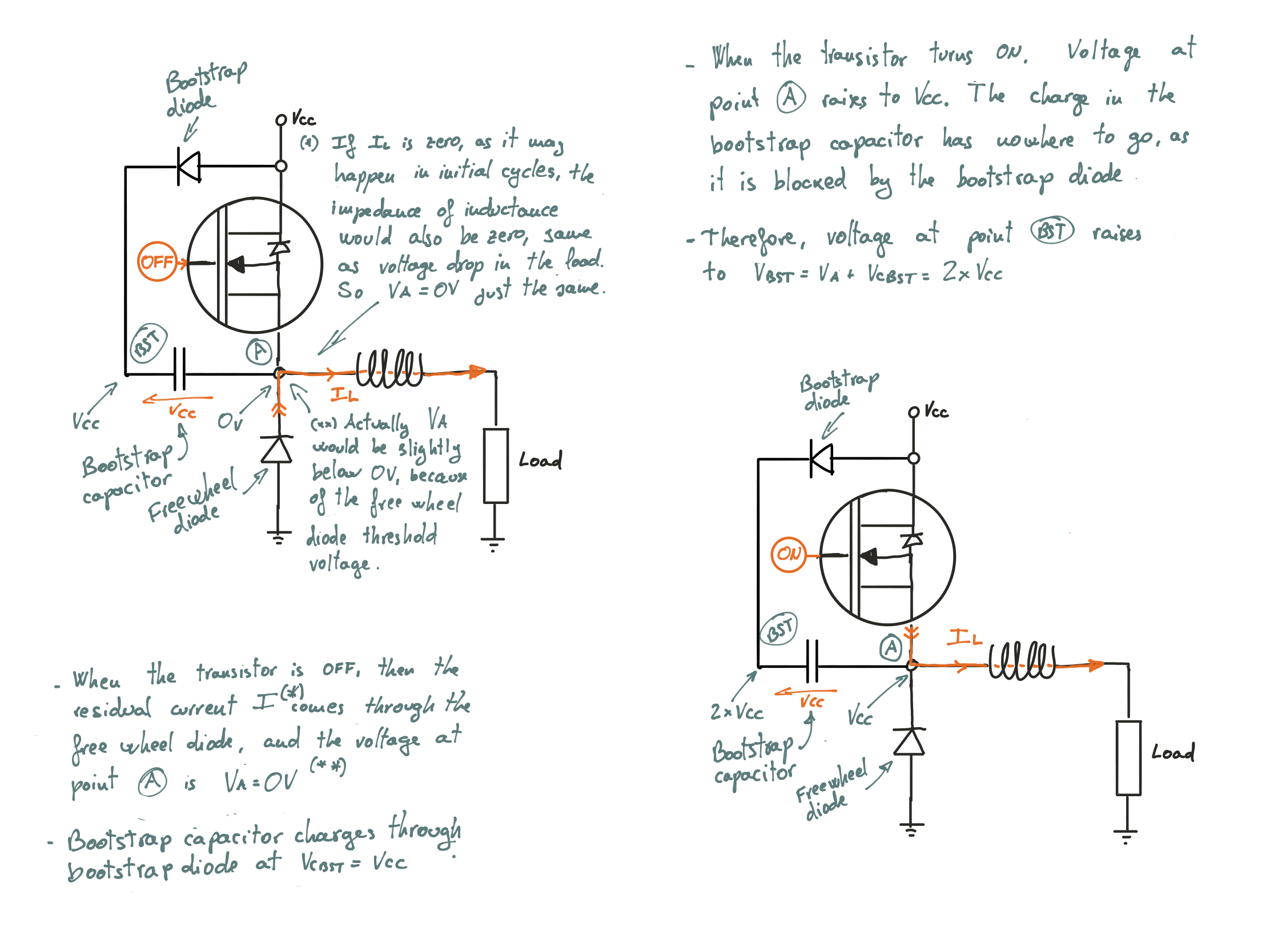
This is what the bootstrap circuitry does - it pushes the gate voltage way above the power voltage.
How it works
I'm borrowing this brilliant explanation from «Electronics Stackexchange - mosfet bootstrap explained» :
If we consider the capacitor initially charges at Vcc through the diode and then never discharges more than a fraction of a volt (if it's not the case, it means it is not appropriately sized), there is always a ~Vcc potential difference across the capacitor, thus between the MOSFET source and the higher transistor's collector, right?
So when the higher transistor goes on, this Vcc voltage is propagated through the gate, and there will be a Vcc potential difference between gate and source. The MOSFET starts conducting.
The MOSFET source will then go up quickly, but the gate will follow, because of the capacitor. So there is still the Vcc potential difference between gate and source, and the MOSFET still conducts. The source and gate voltages are actually "linked" by this capacitor, although most of the circuit is "floating" (referenced on the output voltage).
Note that if the output stays high for too long, the capacitor will discharge too much because of the gate leakage. At some point, the MOSFET may stop conducting. But if the input changes state before this, the output (and source pin) will go down and the capacitor will charge again through the diode, and we can start over.
Only the drawing is mine:

An example
In this example we build a gate driver with a small resistor to connect the bootstrap capacitor to the MOSFET’s gate, and a BJT transistor to discharge the gate:
- When the control signal goes high, the BJT lets pass current and the gate voltage drops to near zero.
- When the control signal goes low, the BJT stops conducting and the gate goes high charged by the bootstrap capacitor.

You can play around with online version here: https://easyeda.com/jmgonet/h-bridge
As explained above, the bootstrap capacitor keeps a potential difference of approximately Vcc because he has either no path to discharge (when control signal is low) or is fed by the bootstrap diode.
This is the result of the simulation:
This driver circuit has the advantage of being simple, but it has three main drawbacks:
- The control signal is inverted; the MOSFET is conducting when the control signal goes low. This alone would not be a major inconvenience, because it is fairly easy to adapt the generation of control signal.
- To switch off the MOSFET, the BJT creates a voltage by letting a current to traverse the driver resistance. As the driver resistance has to be as small as possible (see below), the current is not negligible.
- To switch on the MOSFET, the BJT cuts the current and the bootstrap capacitor charges the gate capacitor through the small resistance. The smaller the resistance, the quicker the switch, and the higher frequency is achievable.
To correctly size this circuit, one has to make a compromise between current consumed when gate is turned off, and maximum frequency.
h1. Using a totem pole configuration
h1. The high and low side driver
Alternatively, if you don't want to compromise high speed with current loss, or you don't want to have too many components to place on your PCB, you can use an integrated circuit called high and low side driver: