Electronic control system (LinuxCNC) - jasonwebb/tc-maker-4x4-router GitHub Wiki
Quick links
MESA 5i25 PCI card - MESA 7i76 breakout - Stepper motor driver - AC relays
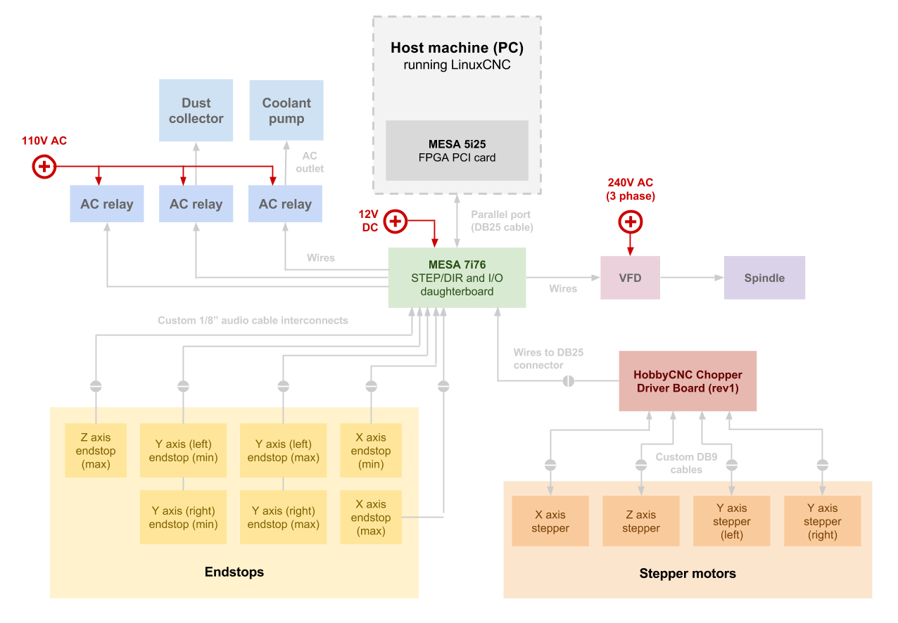
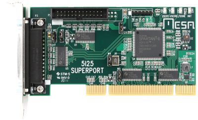
The MESA 5i25 is a high-performance expansion card inside of the host machine PC that is specially designed to provide the computing power needed to efficiently and quickly calculate the complex coordinated movement trajectories (including acceleration profiles, look-ahead planning, and more) of all of the motors. These trajectories are chopped up into very fast "step" and "dir" signals for each motor, which are all output in real-time through the 5i25's DB25 parallel port.
- Supports up to 5 channels of step/dir outputs
- Provides 34 I/O pins (17 per connector)
- All I/O pins are 5V tolerant, with pull-up resistors
- Includes firmware modules such as:
- Hardware step generation
- Quadrature encoder counting
- PWM generation
- Digital I/O
- Visit the product page
- Download the manual from /docs/electronic-control-system-linuxcnc
- Download the support software from /software/electronic-control-system-linuxcnc
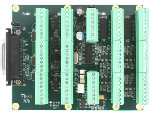
The MESA 7i76 is designed to be a kind of breakout board for the MESA 5i25 (or similar) PCI card, essentially allowing for easier access to the pins its DB25 parallel port.
Nearly all of the DB25's pins are broken out directly to screw terminals for easy access to step/dir signals for all motors, as well as spindle encoder inputs. All other screw terminals connect to an additional microcontroller on the 7i76 whose purpose is to handle additional I/O and pass along data to the 5i25 via the DB25's Smart Serial interface.
- Supports up to 5 stepper motors.
- Isolated analog spindle control, with a spindle encoder interface.
- Supports up to 48 isolated general I/O pins for use with limit switches, control panel inputs, coolant control, and tool changer control outputs.
- On-board RS-422 interface available for additional expansion for a serial I/O daughtercard.
| Header | Functionality |
|---|---|
| TB1 | External power for board. See page 10 of the manual for details. |
| TB2 | Step/dir signals for 4 motors, with +5V and GND for each. See page 5 of the manual for details. |
| TB3 | Step/dir signals for the 5th motor, along with spindle encoder inputs and an RS-422 serial interface for expansion. See page 6 of the manual for details. |
| TB4 | Isolated analog output and control signals for the spindle. See page 7 of the manual for details. |
| TB5 and TB6 | Total of 48 general purpose I/O pins for use with endstops, relays, lighting and more. See page 8 of the manual for details. |

| Pin | Connected to |
|---|---|
| 1 | Rings of all endstop audio jacks |
| 2-4 | - |
| 5 | 12V input from power supply |
| 6-7 | - |
| 8 | Ground from power supply |
| Pin | Connected to |
|---|---|
| 1 | Stepper motor driver ground |
| 2 | - |
| 3 | X step |
| 4 | - |
| 5 | X dir |
| 6-8 | - |
| 9 | Y1 step |
| 10 | - |
| 11 | Y1 dir |
| 12-14 | - |
| 15 | Z step |
| 16 | - |
| 17 | Z dir |
| 18-20 | - |
| 21 | Y2 step |
| 22 | - |
| 23 | Y2 dir |
| 24 | - |
| Pin | Connected to |
|---|---|
| 1 | Ground for ??? |
| 2-23 | - |
| 24 | Ground for AC relays |
| Pin | Connected to |
|---|---|
| 1 | Spindle speed signal ground |
| 2 | Spindle speed signal analog output |
| 3 | Spindle speed signal Vcc |
| 4-5 | - |
| 6 | Spindle enable |
| 7 | Spindle direction (inverted) |
| 8 | - |
Not used
| Pin | Type | Connected to |
|---|---|---|
| 1 | Input | Endstop ??? signal |
| 2 | Input | Endstop ??? signal |
| 3 | Input | Endstop ??? signal |
| 4 | Input | Endstop ??? signal |
| 5 | Input | Endstop ??? signal |
| 6 | Input | Endstop ??? signal |
| 7 | Input | Endstop ??? signal |
| 8-16 | - | - |
| 17 | Output | Trigger for dust collector's AC relay |
| 18-24 | - | - |
- Visit the product page
- Download the manual from /docs/electronic-control-system-linuxcnc
The machine uses a HobbyCNC PRO Rev1 Chopper Driver Board to efficiently control the stepper motors. This board takes as inputs two logic-level (5V) signals per motor - one to tell the appropriate motor driver to "step", and one to tell it what direction ("dir") to step in (clockwise or counter-clockwise).
Whereas it is the job of the 5i25 PCI card inside of the PC to generate these low voltage signals, and the 7i76 daughtercard's job to distribute and pass along these signals, it is the job of the chopper driver board to translate these signals into high voltage, high current signals to turn the motors.
NOTE: The Rev1 version of this board is no longer being manufactured, and documentation is scarce. Be prepared to do some sleuthing if you need additional insight beyond what is provided here!
- DC chopper drive control of up to 4 unipolar or bipolar stepper motors.
- Accepts step/dir signals for direct control of motors.
- Accepts 5, 6, or 8 wire stepper motors. 4 wire motors are not compatible.
- Adjusts current to 50% when idle for 10 seconds (time delay is adjustable).
- On-board connectors for endstops come with built-in 10k pull-ups.
-
Current ratings (individually adjustable)
- Maximum = 3.0A per phase
- Minimum = 500mA per phase
- Microstepping = 1/1, 1/2, 1/4, 1/8, and 1/16
- Download the manual from /docs/electronic-control-system-linuxcnc
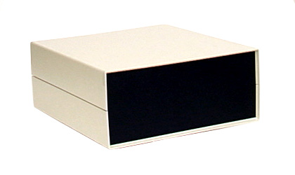
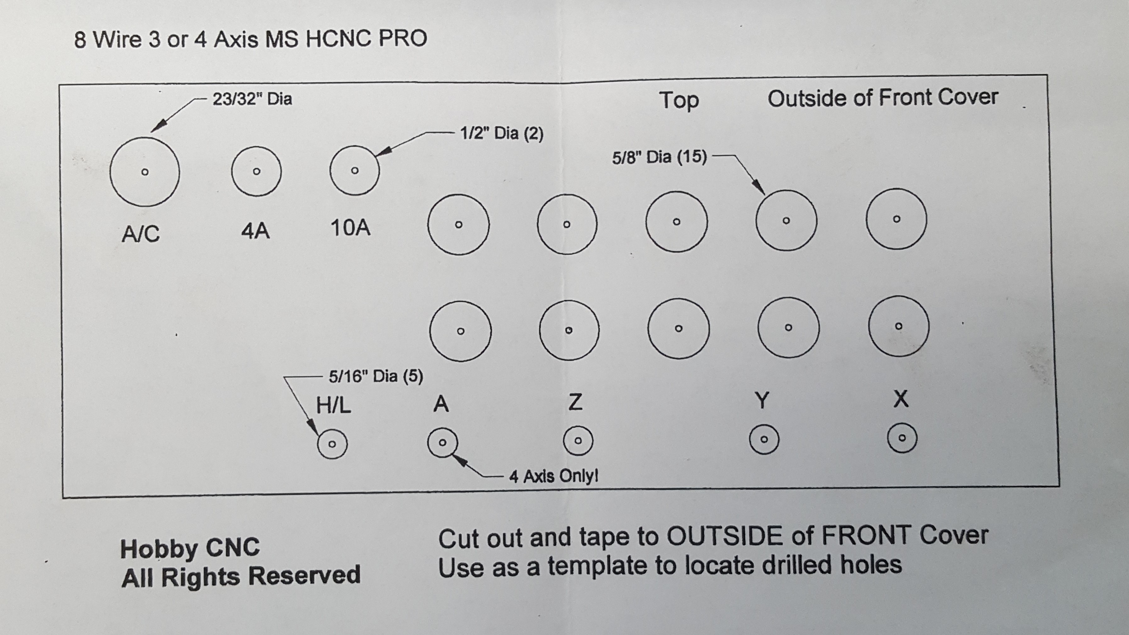
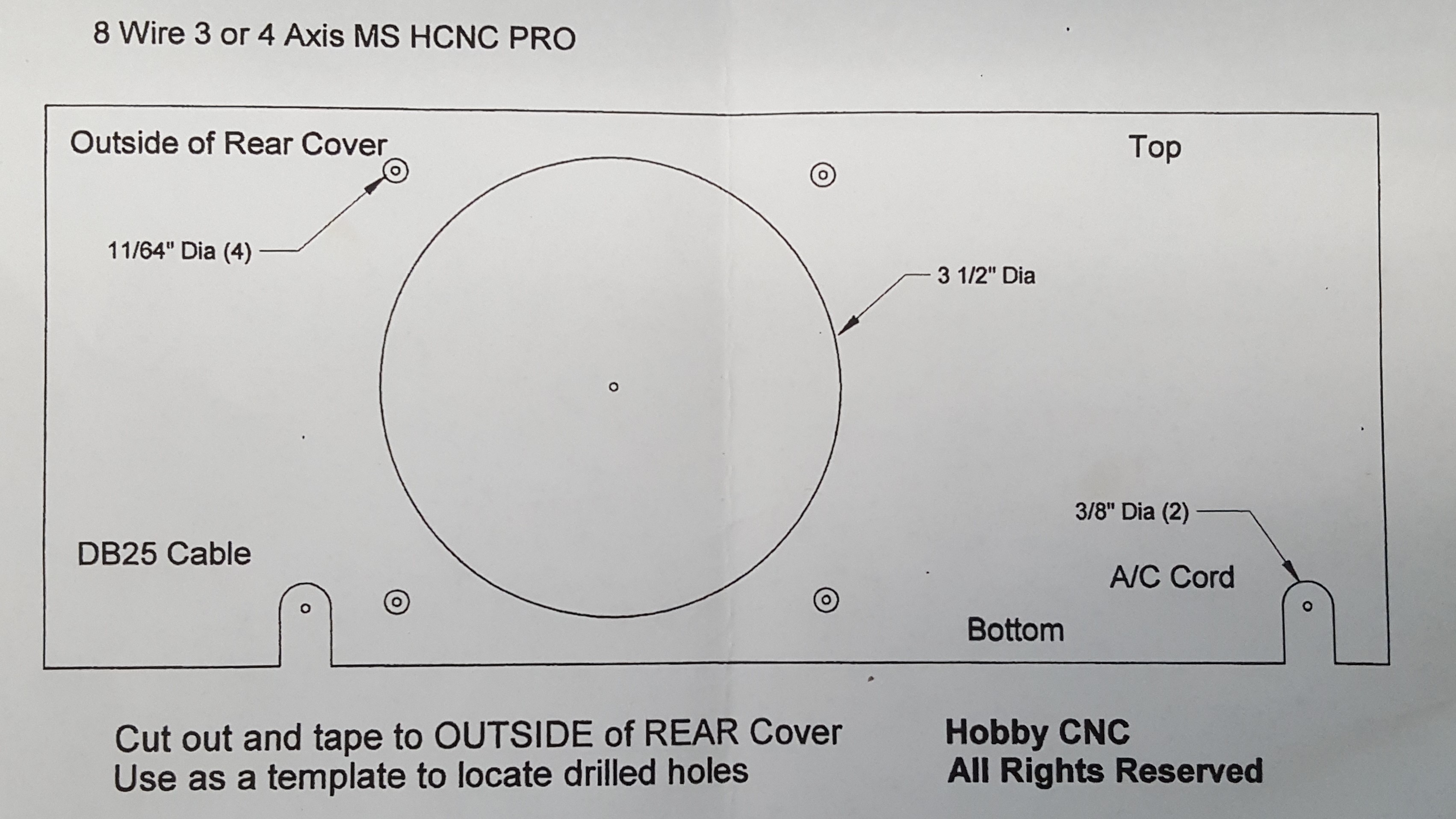
The stepper driver board is housed in a Pactec DM-4 enclosure with a custom design handcut into the front and back panels. These designs are available in the media/electronics folder of the repo.
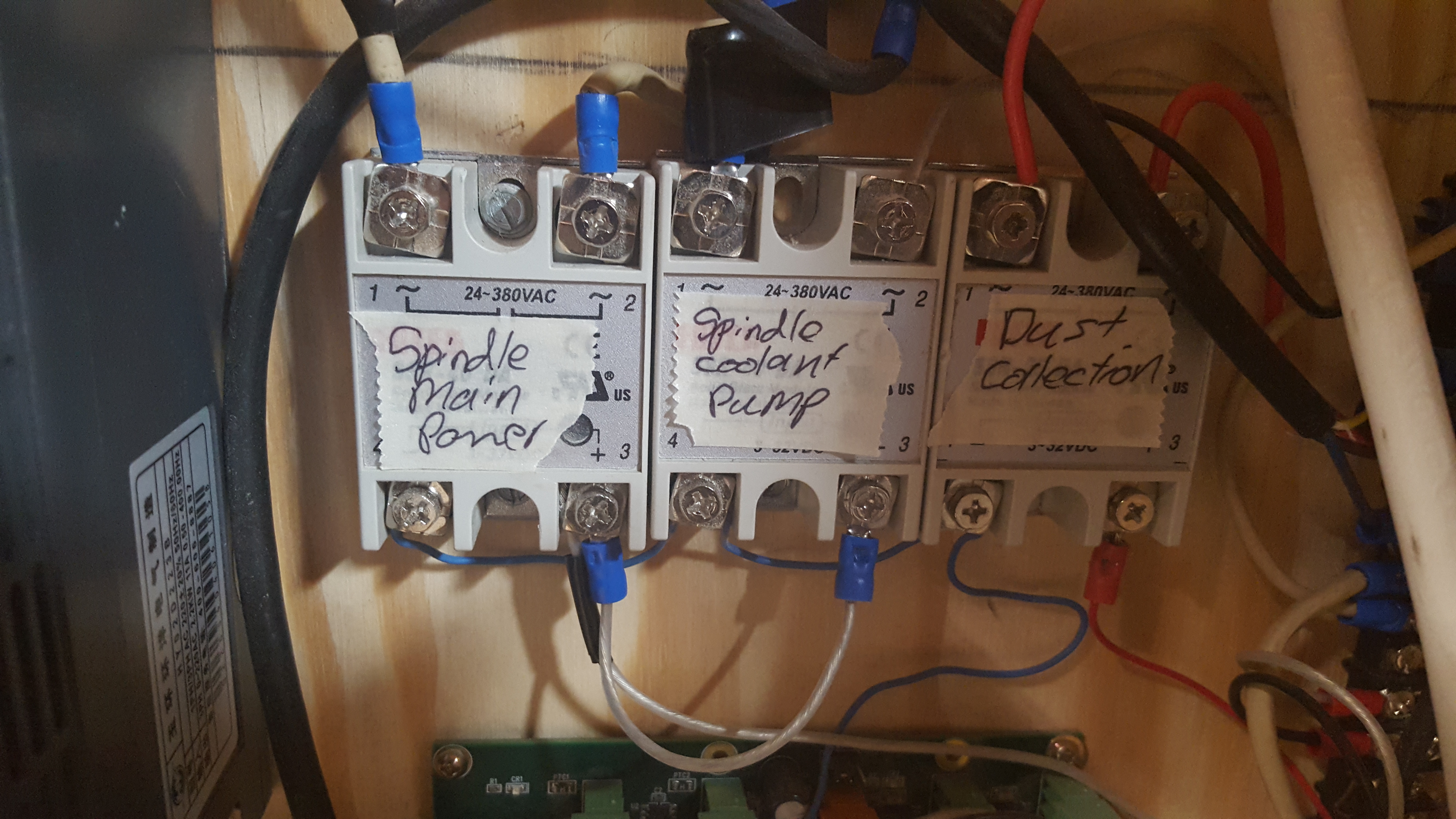
We use three solid-state relays (SSRs) to turn on and off various AC devices using low-voltage DC signals via the 7i76, effectively allowing for control of such things as the dust collector and coolant pump using LinuxCNC.
- Model number - SSR-40A DA
- Maximum AC current - 40A
- Trigger voltage - 3-32VDC
- Trigger current - 7.5mA at 12VDC
| AC device | Triggered by |
|---|---|
| Spindle power | Switch on interconnect panel labelled "Spindle" |
| Coolant pump | Connected to spindle power trigger |
| Dust collector | MESA 7i76 header TB6, pin 17 (OUTPUT0) |