Kinematics model overview - jasonwebb/grbl-mega-wall-plotter GitHub Wiki
Reference mechanism
If you want to use grbl-mega-wall-plotter in your project you must ensure that your design conforms to the following reference diagram:
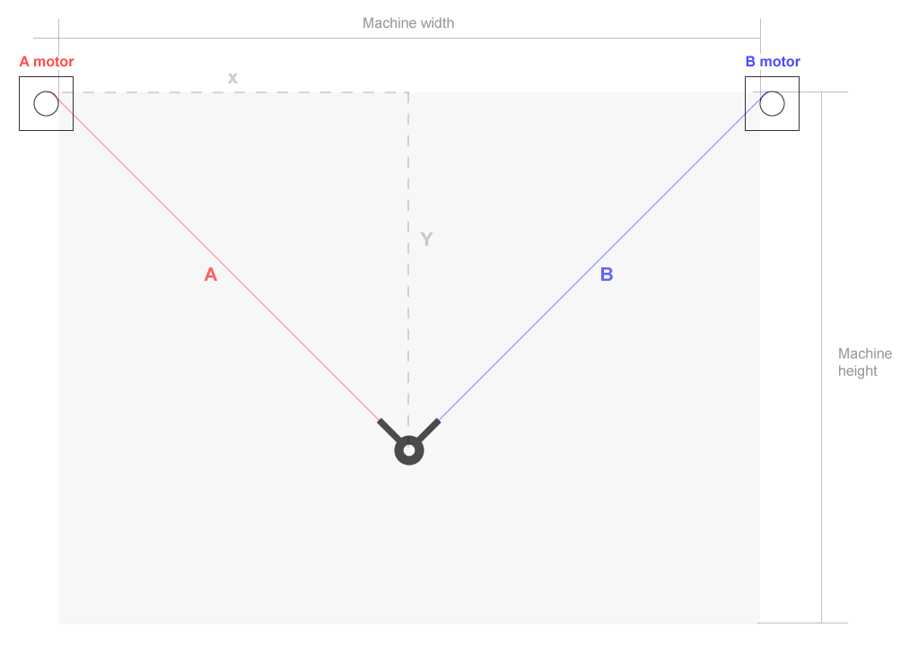
Note that the total lengths of A and B measure from the outer edge of the appropriate pulley to the center of the gondola in order to simplify calculations. You may decide that you want your drawing implement to be in a different location on the gondola, so be aware that doing so will introduce a translation or offset to the drawing that you may want to account for in CAD.
Also note that you can decouple the location of the stepper motors and the location at which you measure the machine's width using idler bearings. If you do, make sure that you are measuring at the correct spots and that you use a bit of extra string/belt to account for the actual extra length needed.
Kinematic equations
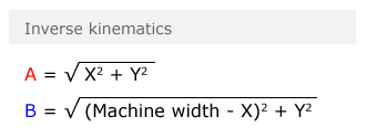
grbl-mega-wall-plotter expects that all G-code commands fed to it are in normal X,Y (Cartesian) coordinates, and will automatically convert these coordinates to line lengths using the following formulas.
Grbl implementation
In the DEFAULTS_WALL_PLOTTER group in defaults.h, the following values are used:
DEFAULT_X_MAX_TRAVELstores the machine width (in mm).DEFAULT_Y_MAX_TRAVELstores the machine height (in mm). This isn't actively used in any calculations right now, but may conceivably be used to calculate a soft limit in the future.
Upon initialization of the firmware the value of DEFAULT_X_MAX_TRAVEL is automatically copied into settings.max_travel[X_AXIS] for use in calculations that take place in planner.c and system.c.