Assembly - ipibo/BattleBitsWorkshop GitHub Wiki
BattleBitsWorkshop wiki!
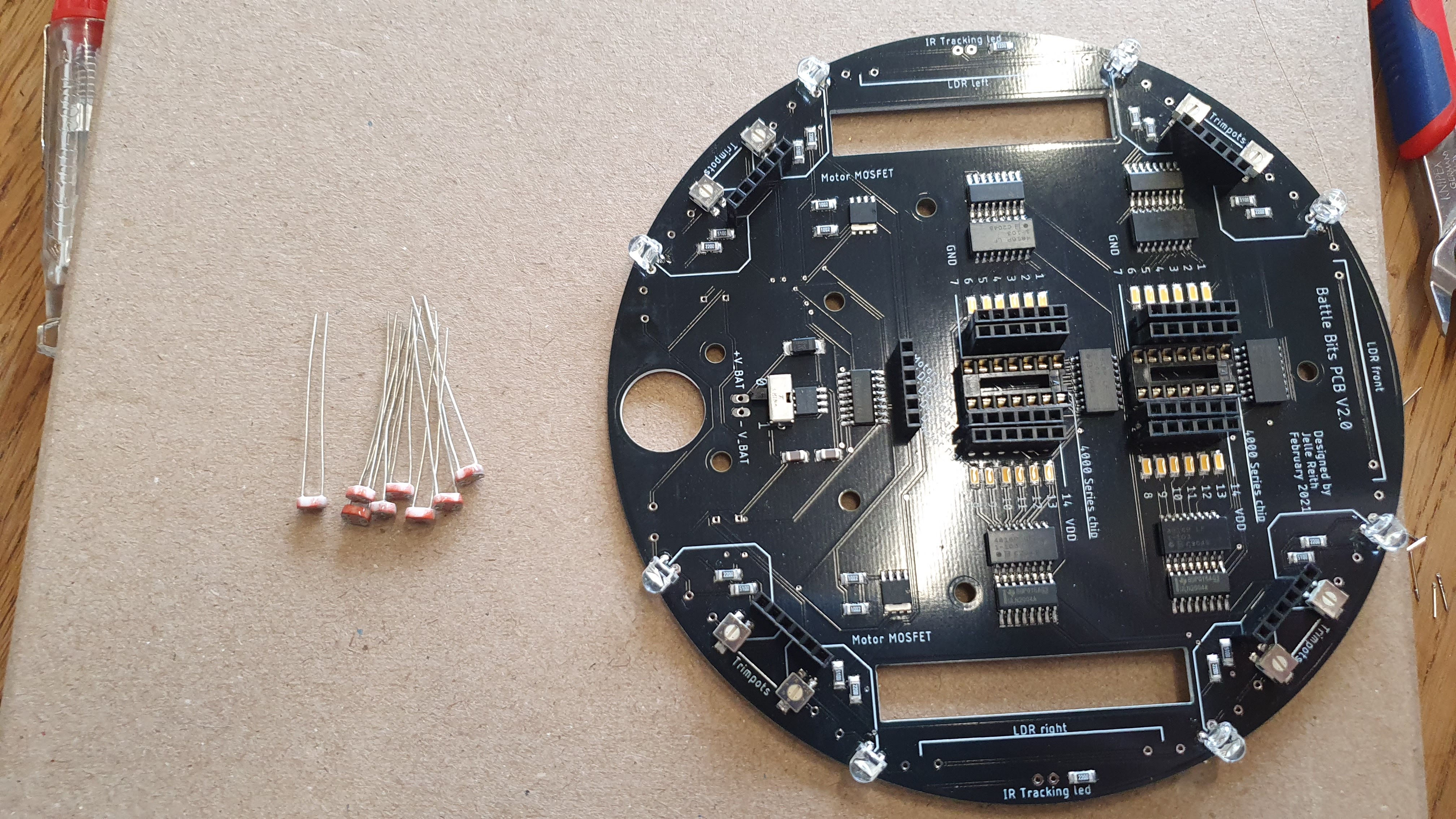
Contents of the package
Your kit should contain the following items:
- 13 x 6 pin female Headers
- 1 x White wire
- 2 x Yellow Gear Motors
- 1 x Wheel base
- 2 x Dip-14 socket
- 8 x 5mm warm white LED and 2 x 5mm IR Led (not in the picture!)
- 1 x 9v battery connector
- 1 x On/Off switch
- 4 x m3 30 mm bolts
- 9 x m3 hex nuts
- 4 x m3 10 mm bolts
- 1 x m3 18 mm bolt
- 8 x LDR ( light-dependent resistor)
- 2 x 50mm o-ring
- 2 x Wheels
- 1 x Battle Bit PCB

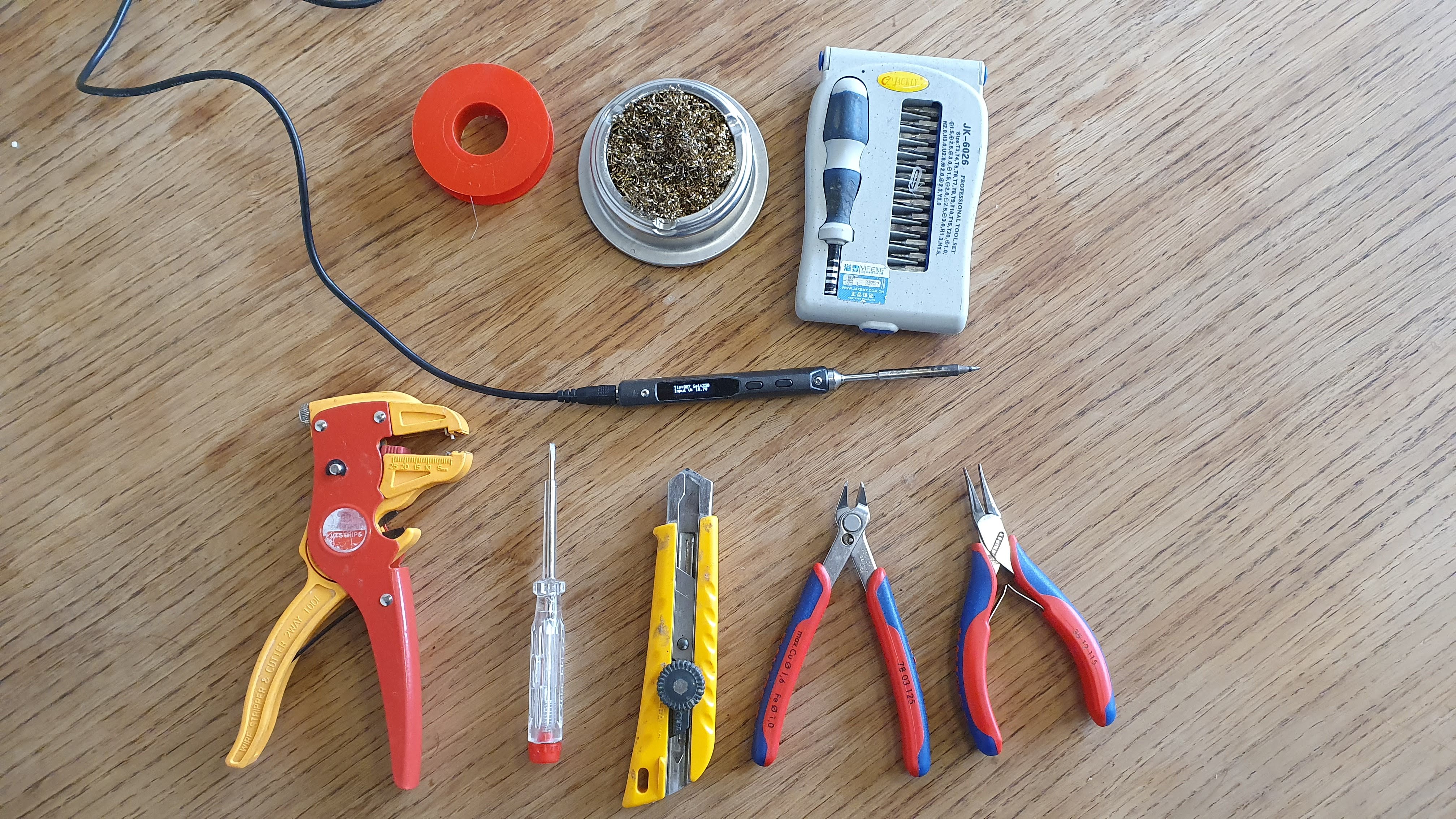
Tools Needed:
- Solder iron
- Soldering tin
- Set of small screwdrivers or a small bit-set
- Couple of pliers
- Stanley knife/utility knife
Manual:
This is a detailed manual for assembling the BattleBit. If there are any questions feel free to ask Ibo or Jelle!
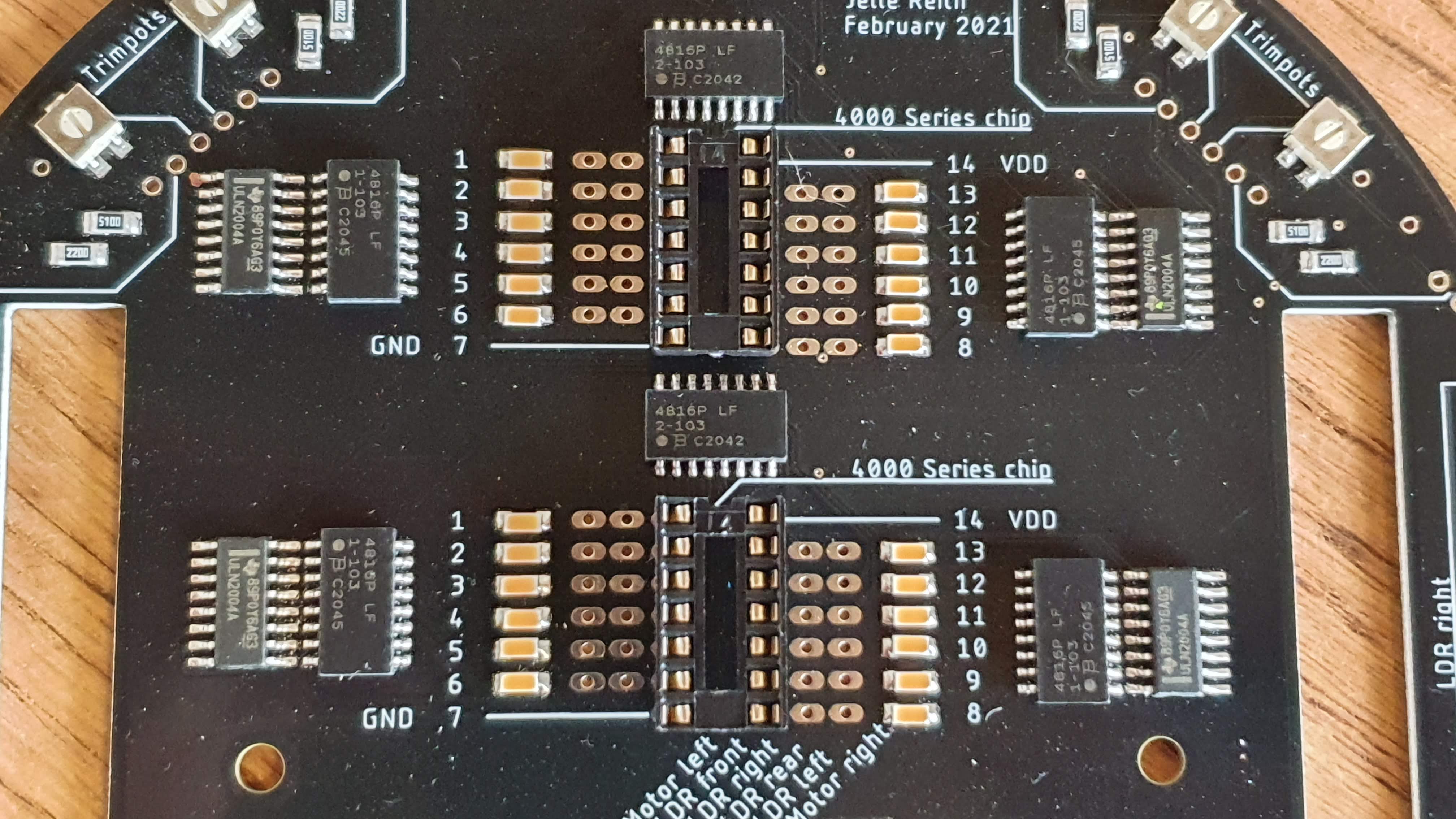
Soldering Dip-14 sockets
The sockets will be used to mount the logic gates of the vehicle.
Place the sockets as follow on the PCB. Make sure the notch of the socket is facing forwards
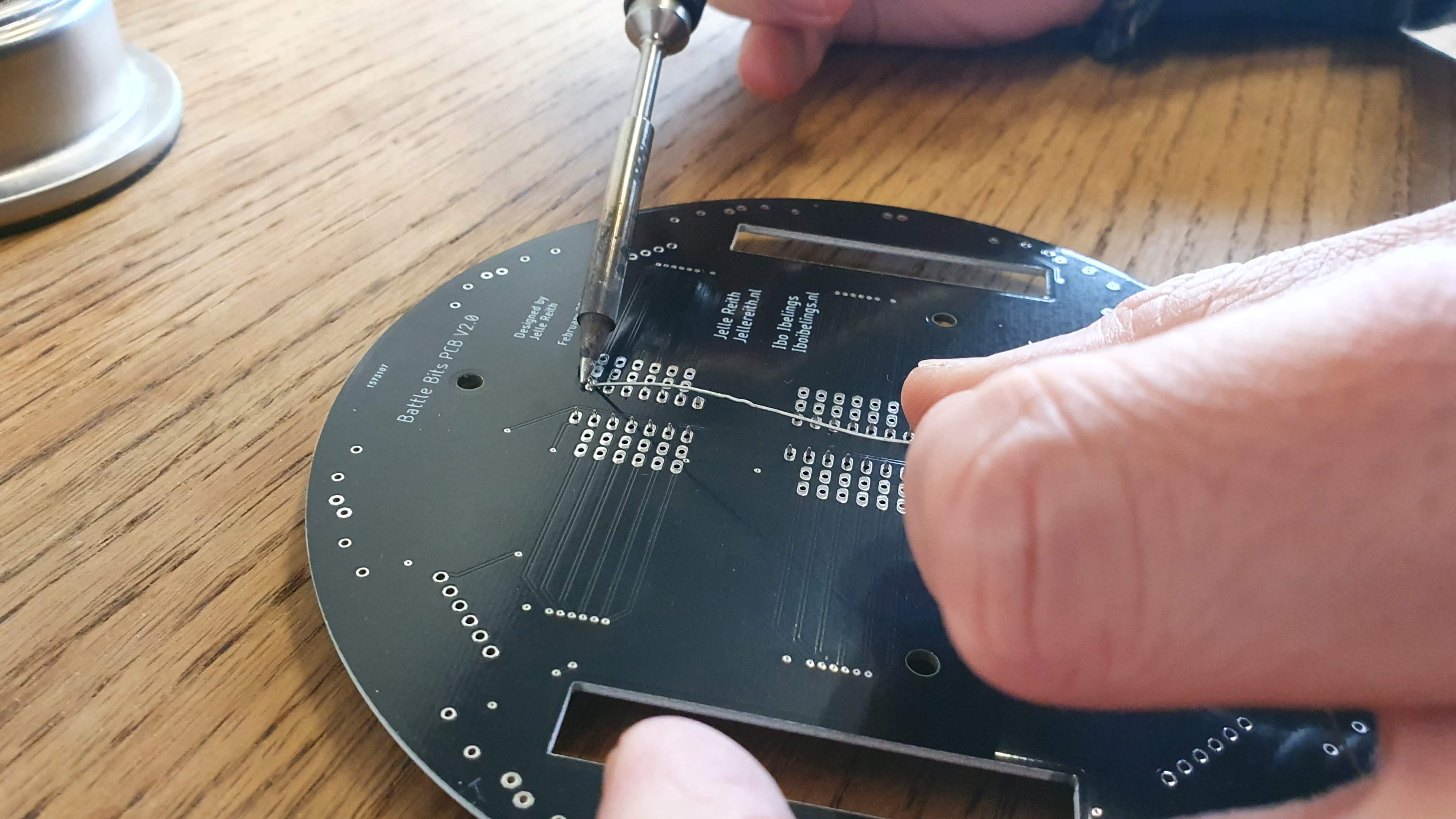
Solder two diagonal pins of the sockets (E.G. pin 1 and 8)

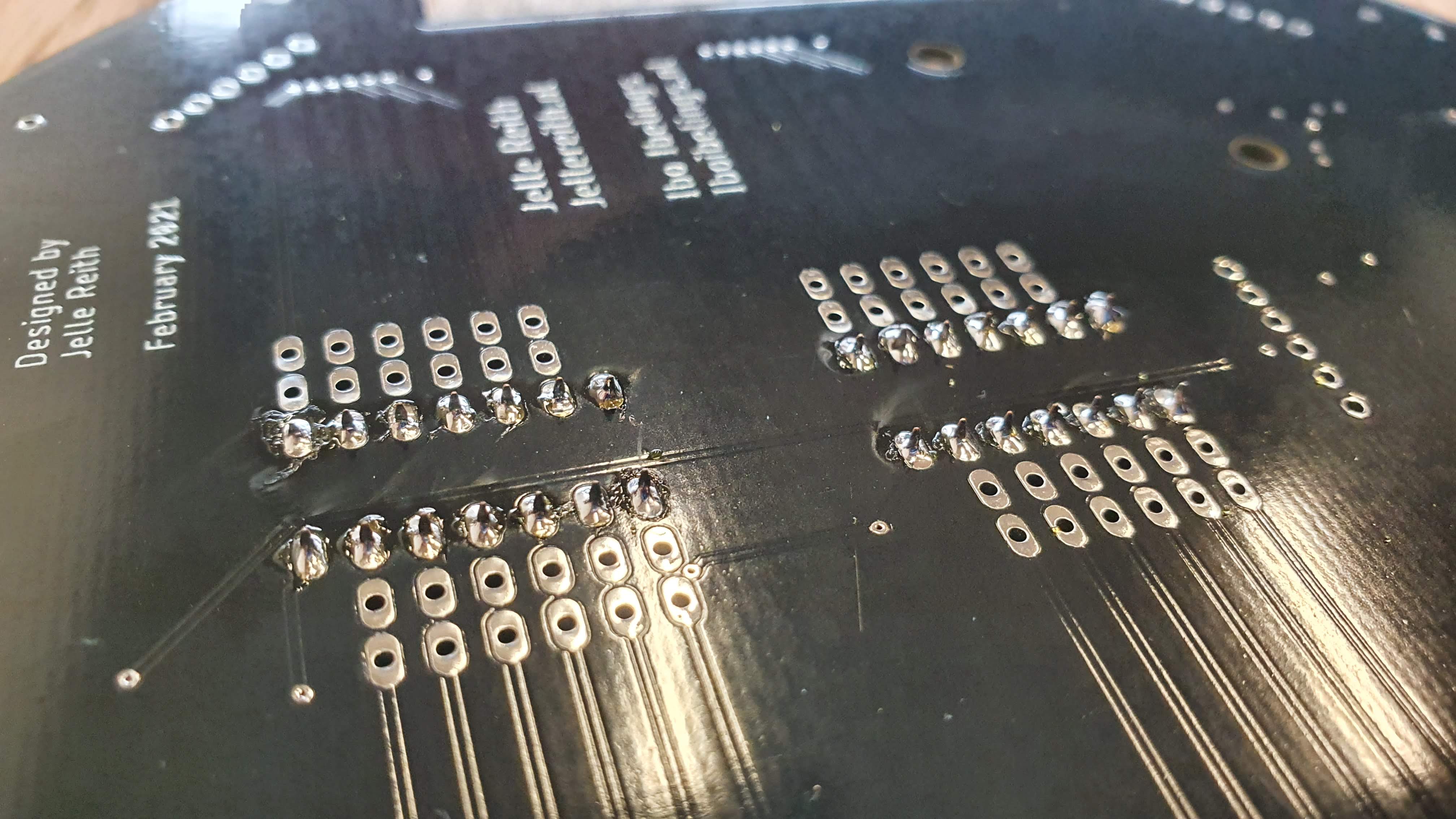
Check if the socket is laying flat on the PCB, so not like this:
 Solder all other pins:
Soldering the pin headers
Place all 13 headers

Flip the PCB upside down
Solder one pin per header
Check if all headers are perpendicular to the pcb
Like:
 And not like:
Solder all other pins
Soldering On/Off switch
Place on/off switch:
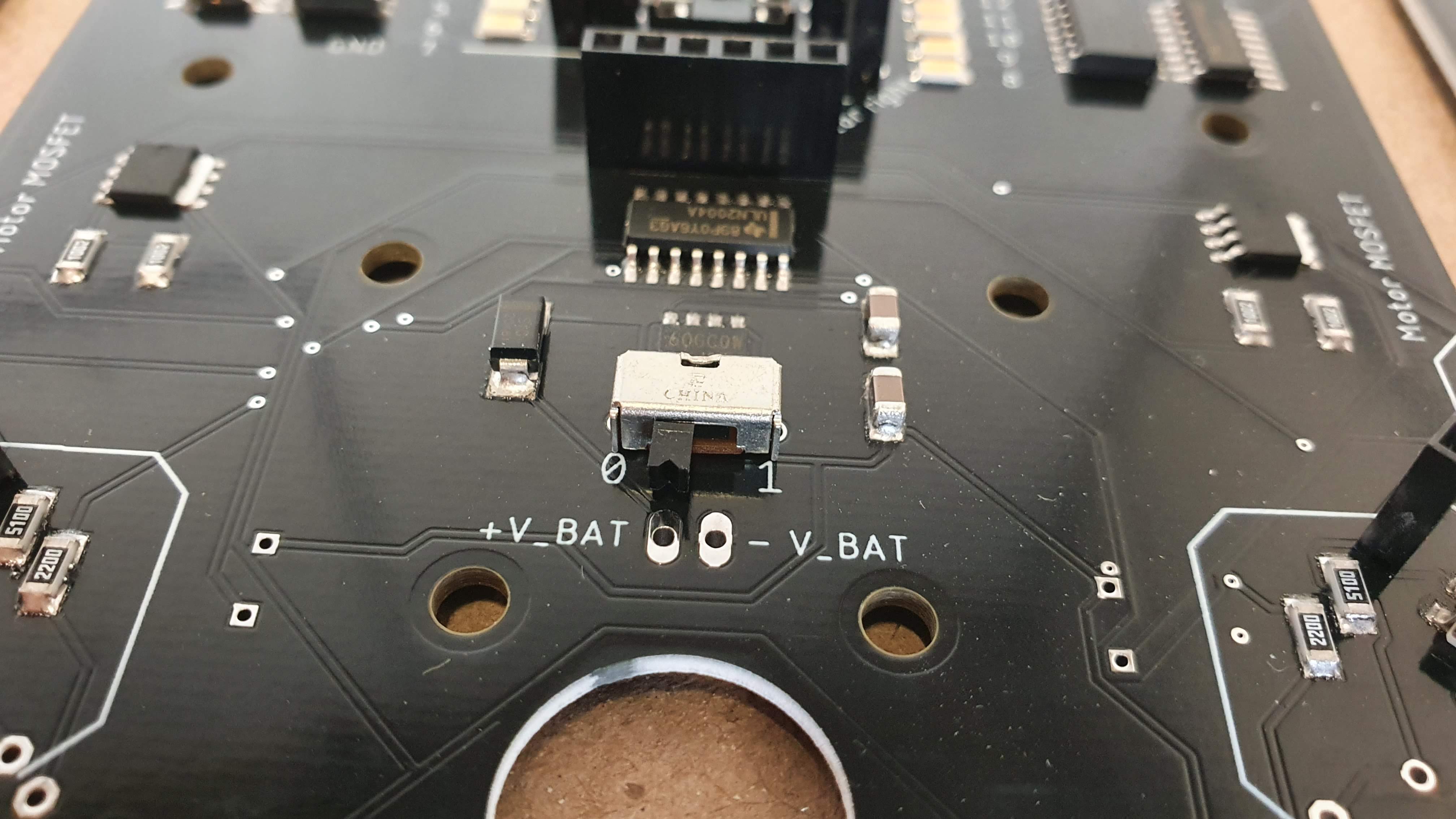 Solder the pins on the board.
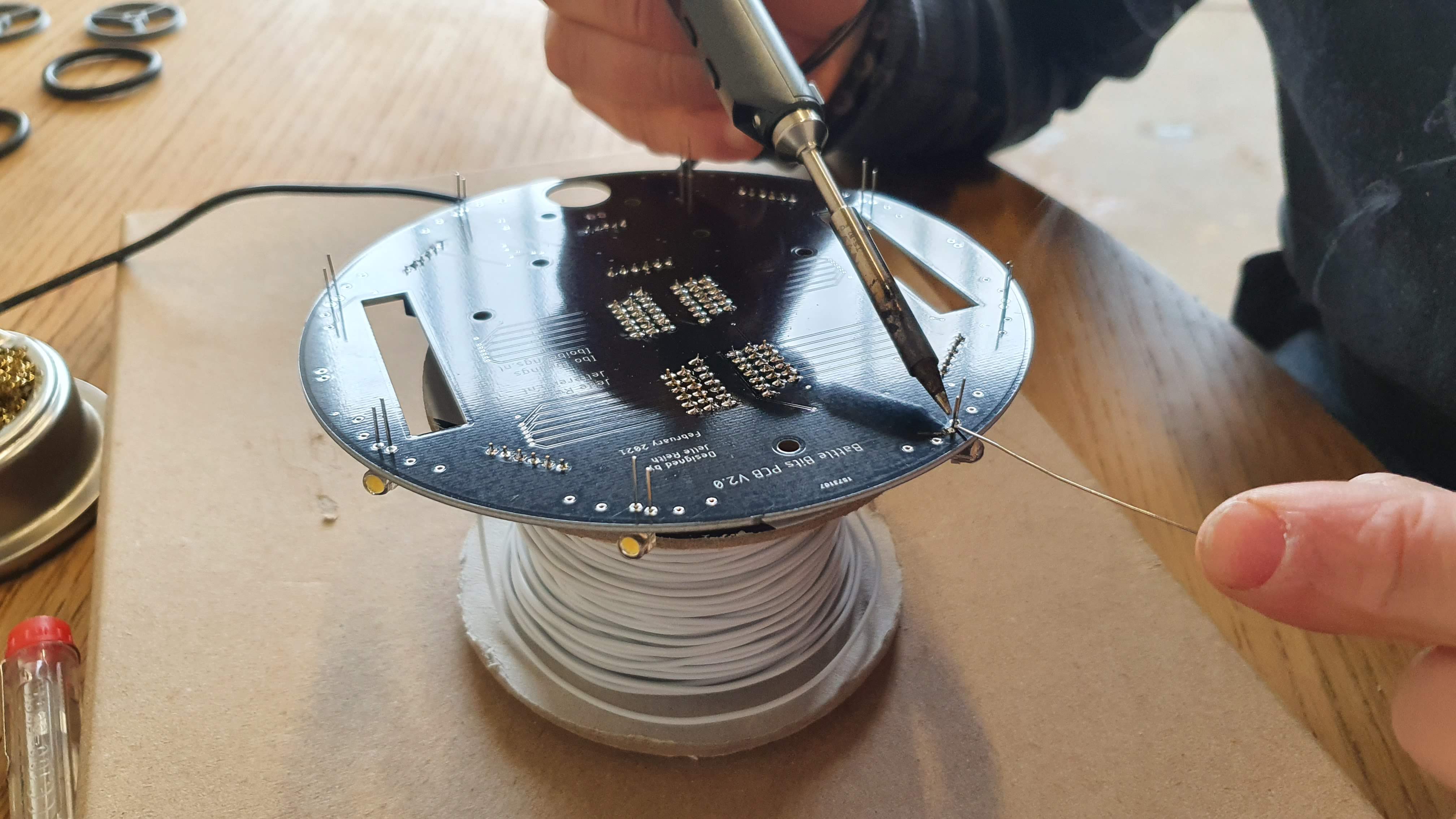
Soldering the 8 warm white LEDs
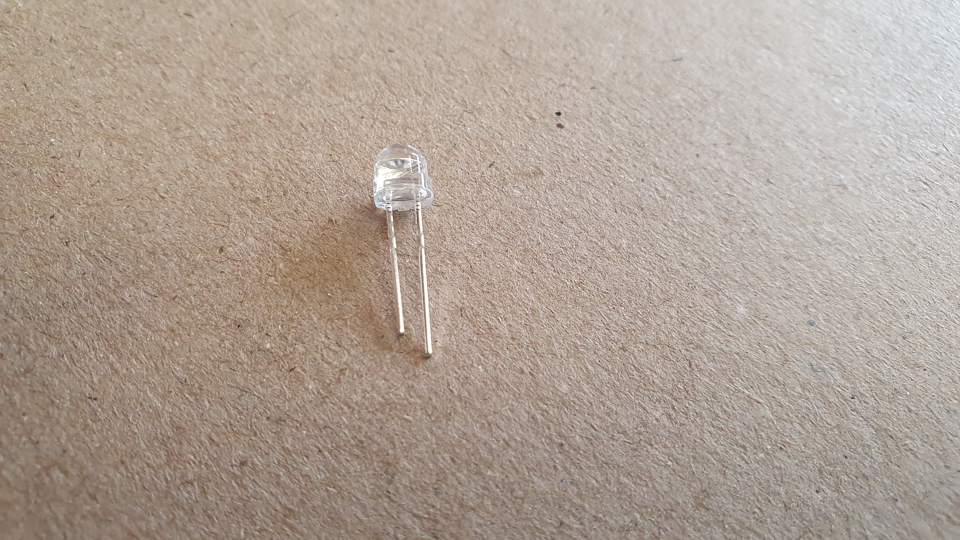
LEDs have a polarity. Make sure that the anode (positive, longest pin) and the cathode (negative, shortest pin) are correct!
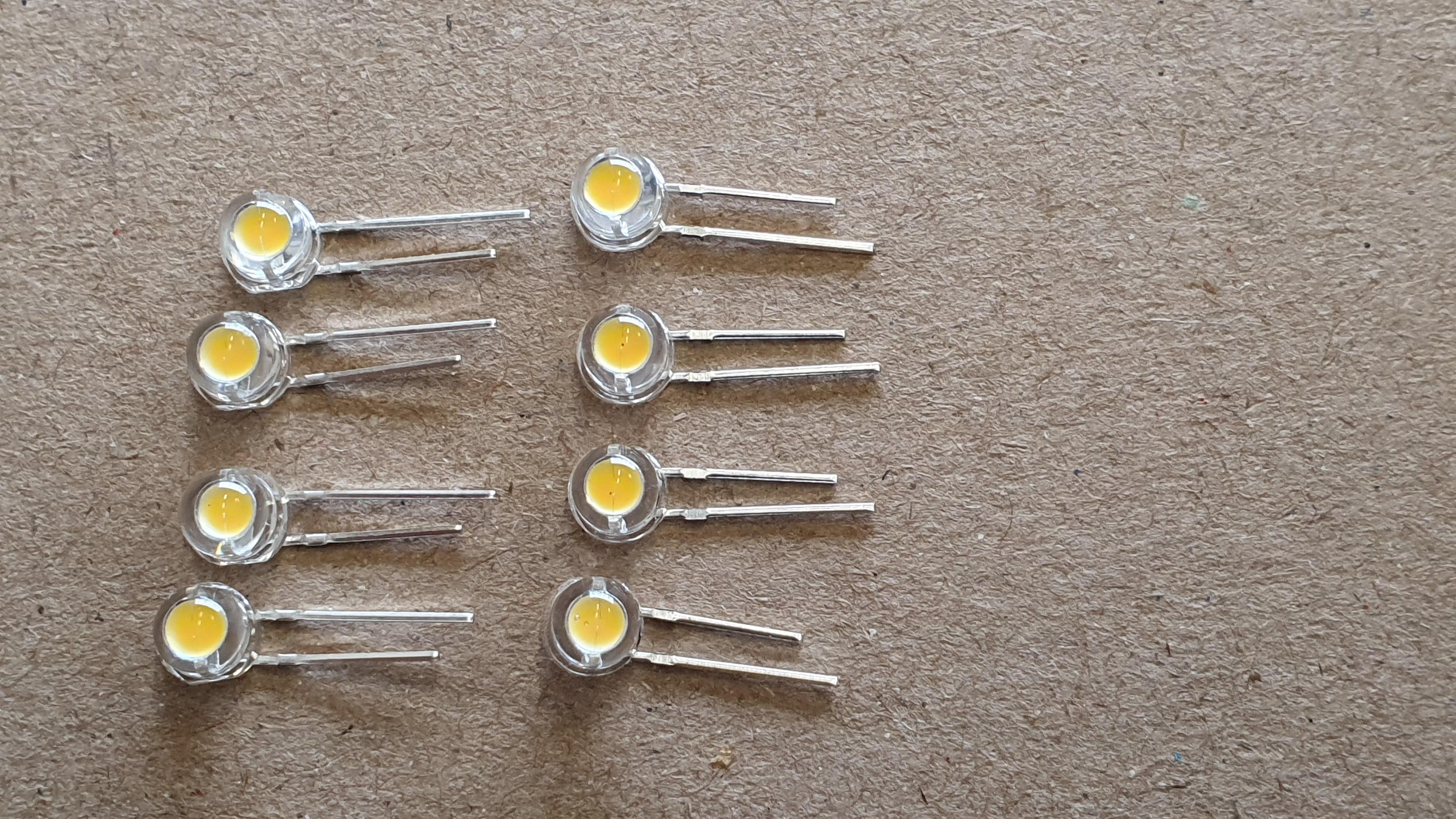
Bend the legs of the LEDs. Bend 4 LEDs with the cathode on the right, and bend 4 LEDs the other way around with the anode on the left
Place the LEDs on the PCB as shown on the picture. Make sure the polarity is correct!
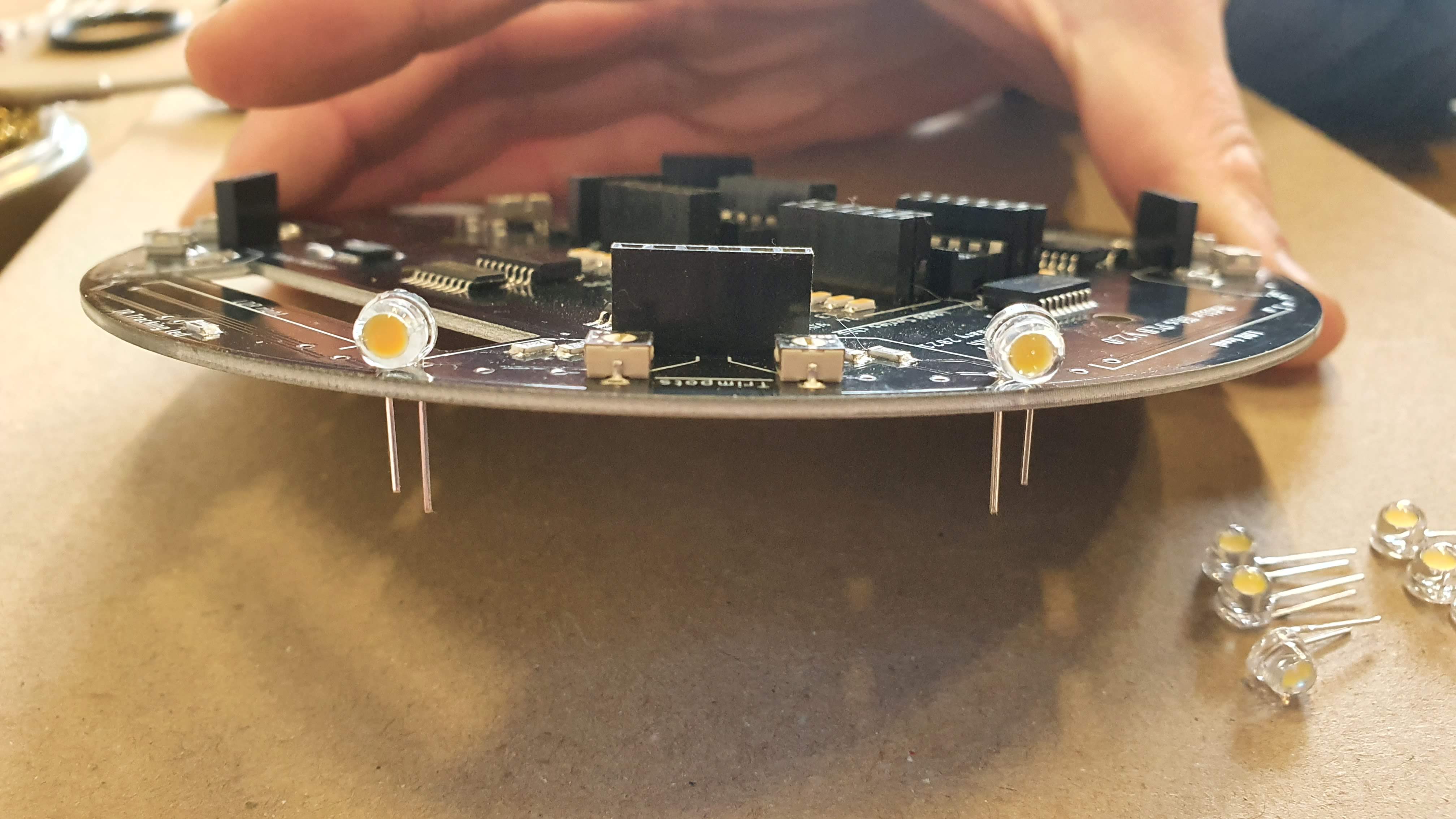
Solder 1 pin
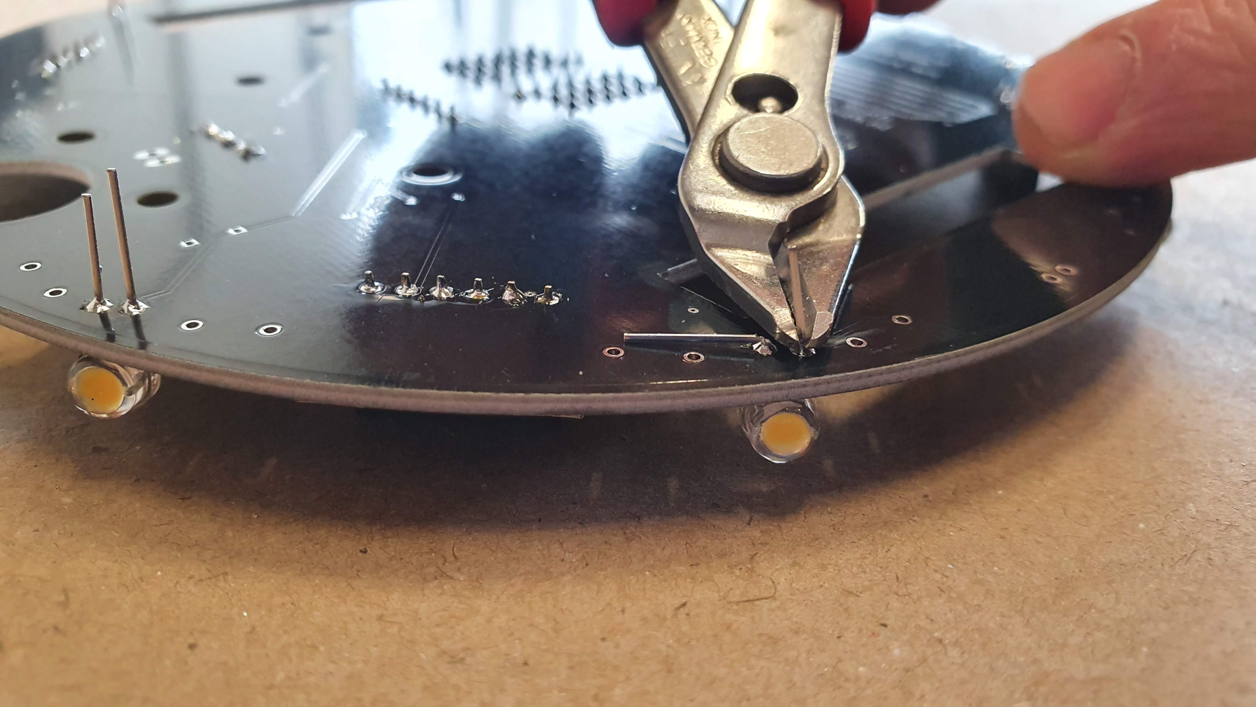
- Check if the LEDs are laying flat on the PCB
- Solder the rest of the pins
- Trim the legs of the soldered LEDs
before the next step you have to put a shrinking tube around the IR tracking LED.
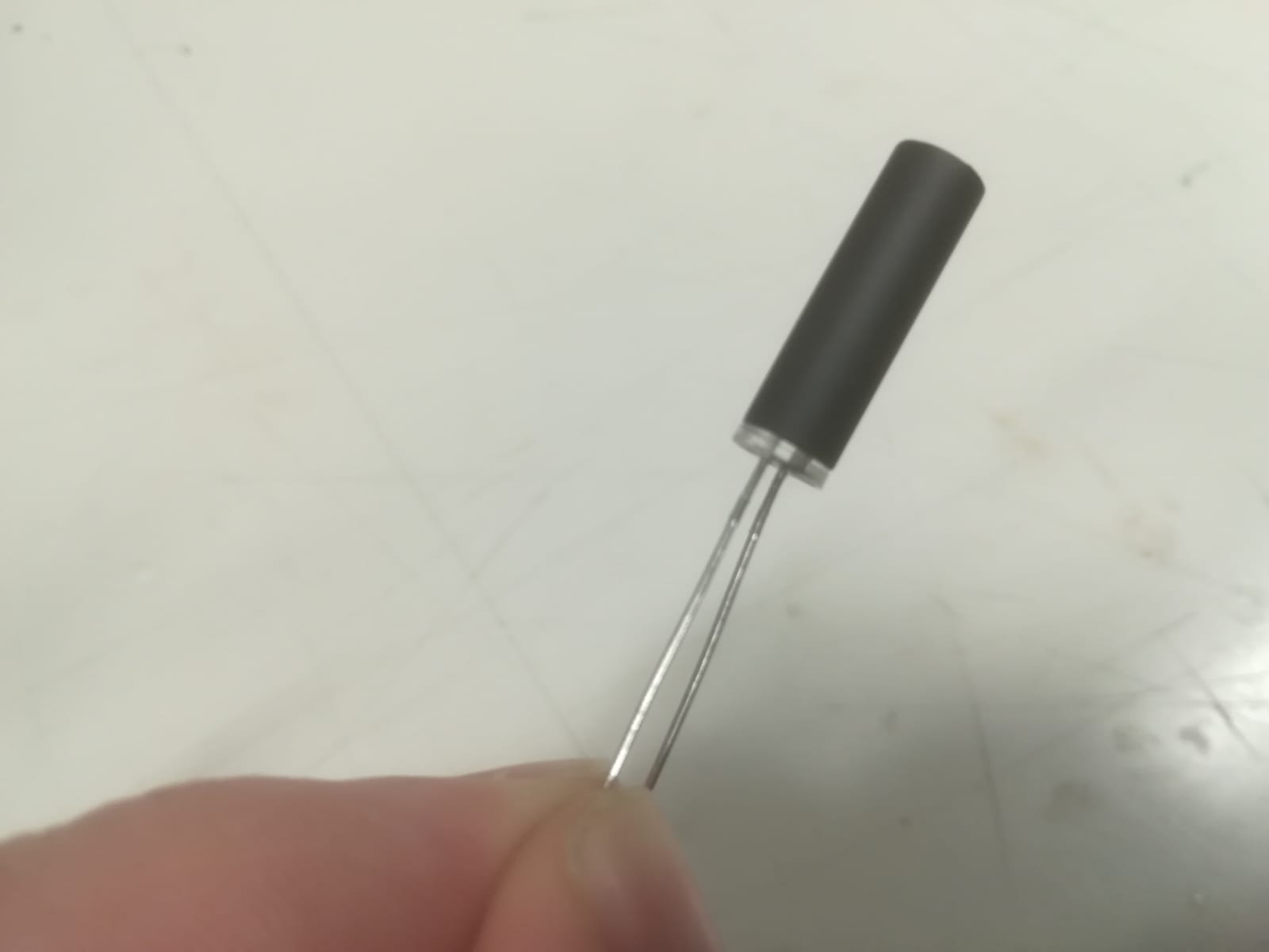 Shrink the tube with some heat of your soldering irong
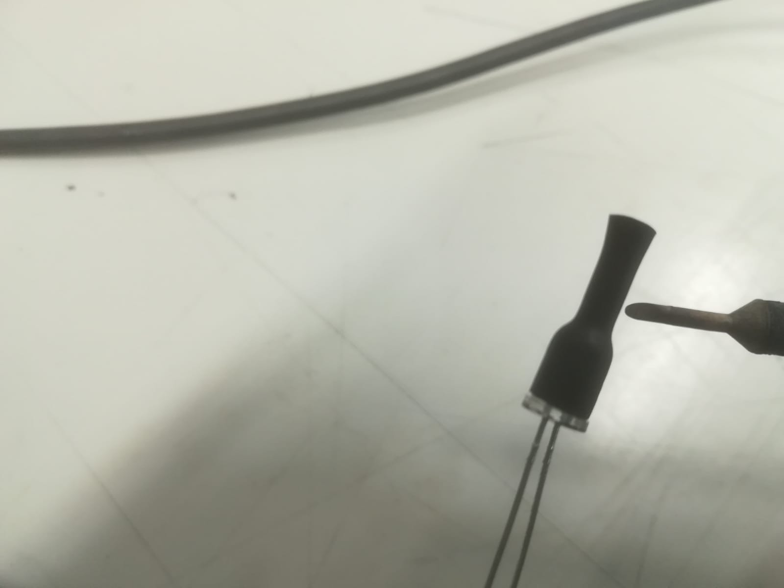 Cut it to length of the IR LED
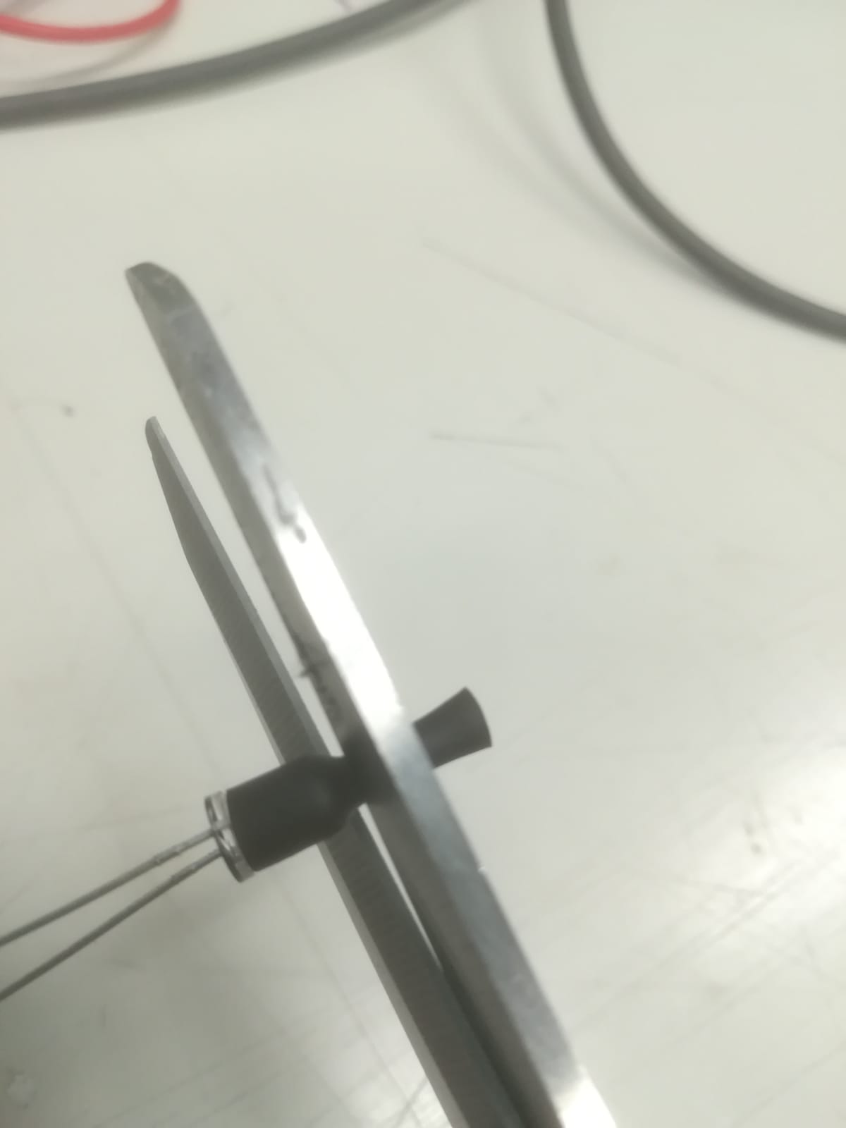
The last step is to solder the two IR tracking LEDs. Unfortunately there aren't any pictures of this step. On the outer perimeter of the PCB look for "IR Tracking led. Just above or below that text there are two holes and one small black resistor with the numbers 2200 (220 ohm). Place the IR Led with the cathote (shortest leg) towards the resistor. Make sure the LED is flat on the pcb and solder in place.
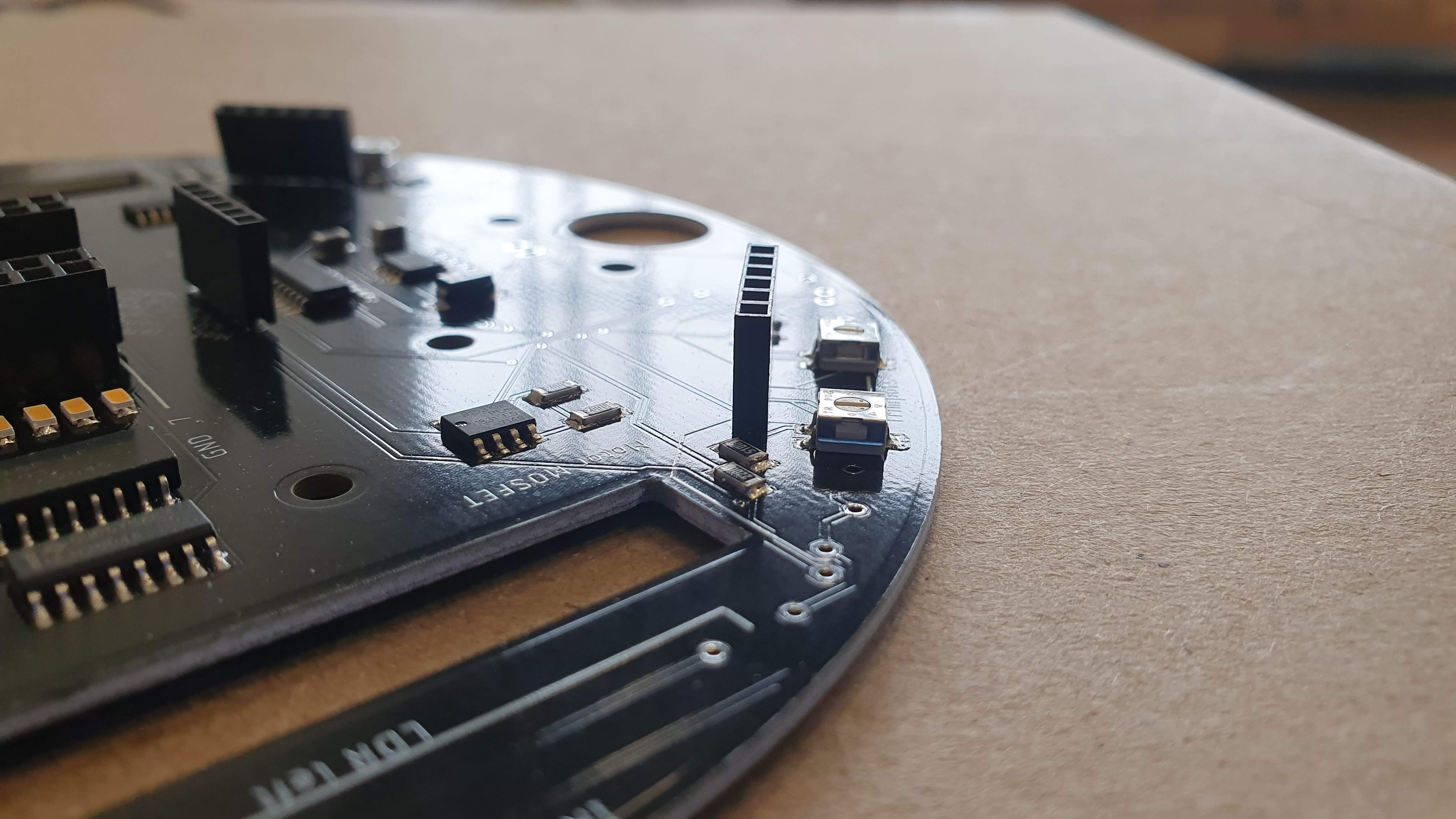
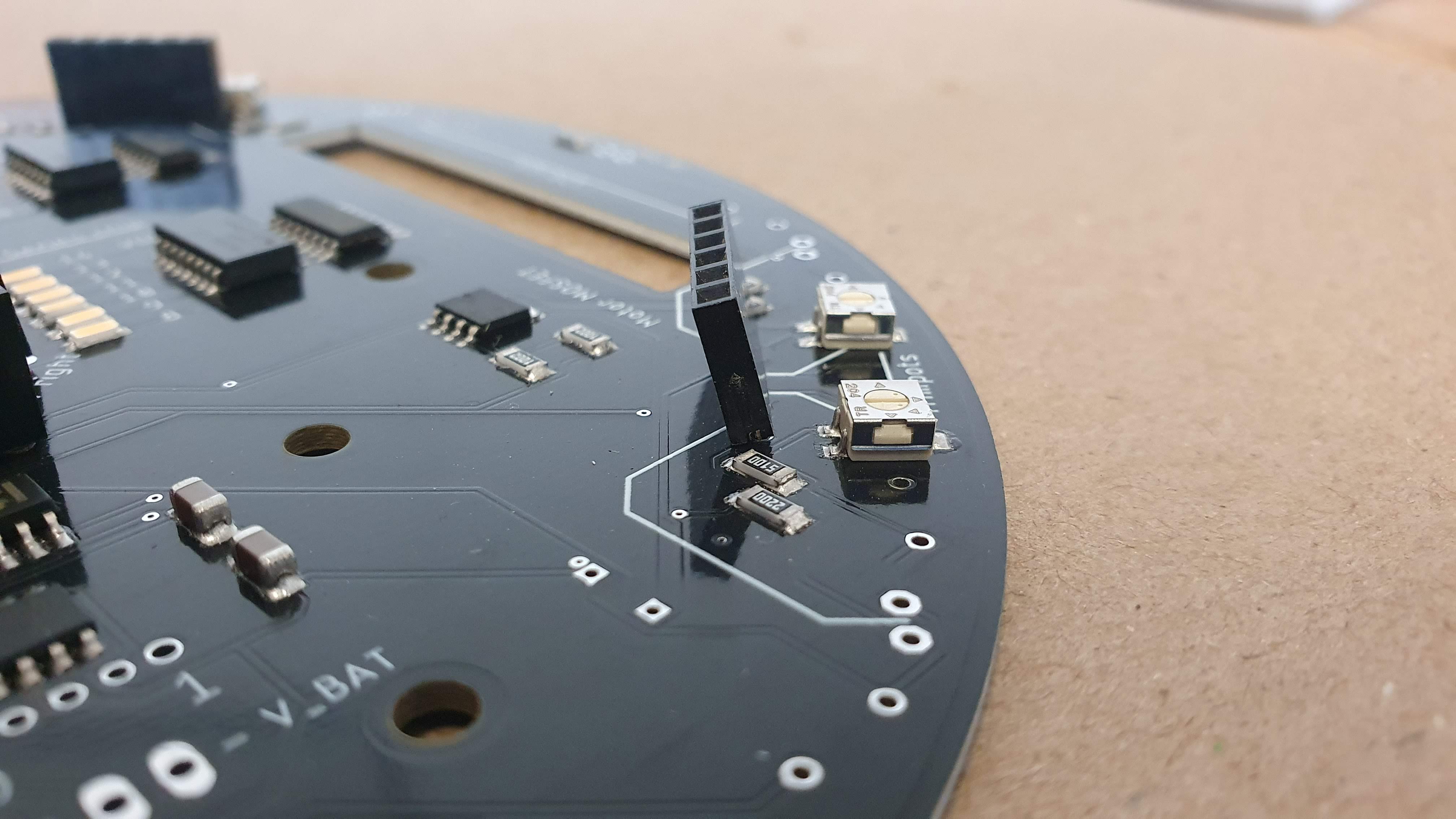
Soldering the Light Dependant Resistors (LDRs / Photoresistor)
 Bend the legs of the LDRs. LDRs don't have a polarity so it doesn't matter which way you bend them.
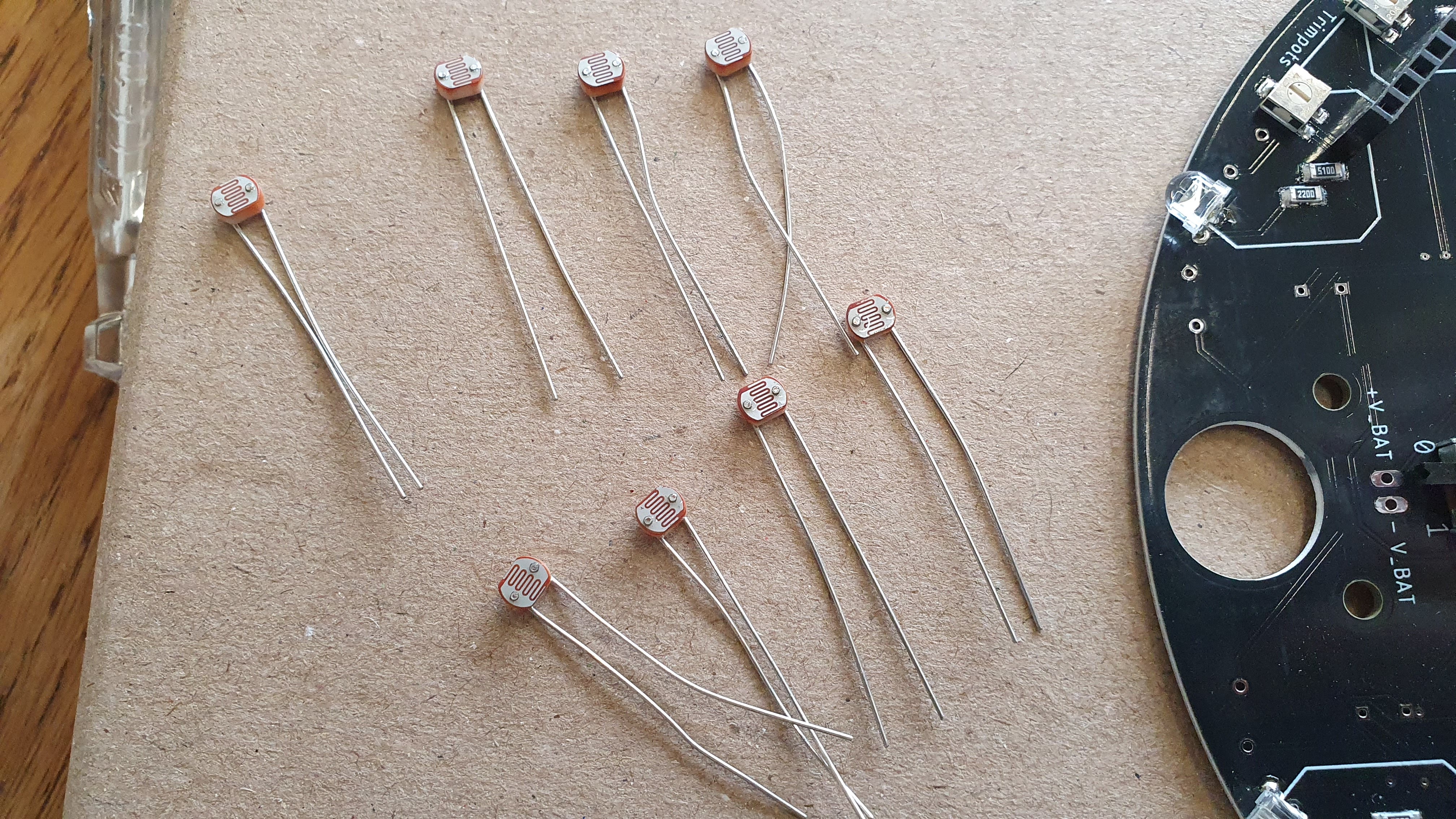 Place the LDRs in de following way
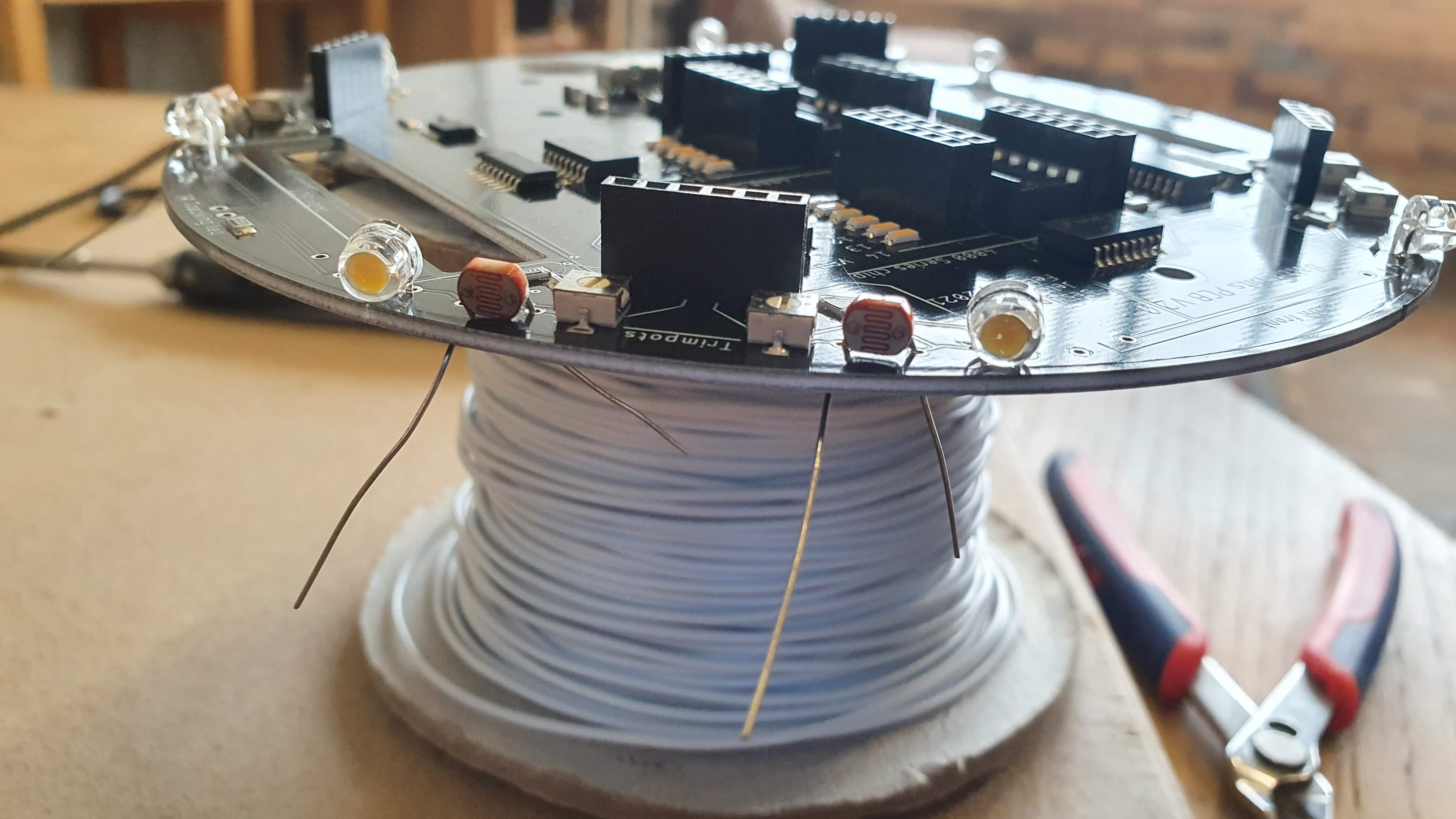
- Solder 1 of the legs
- Check if the LDR is laying flat on the pcb
- Solder the other legs
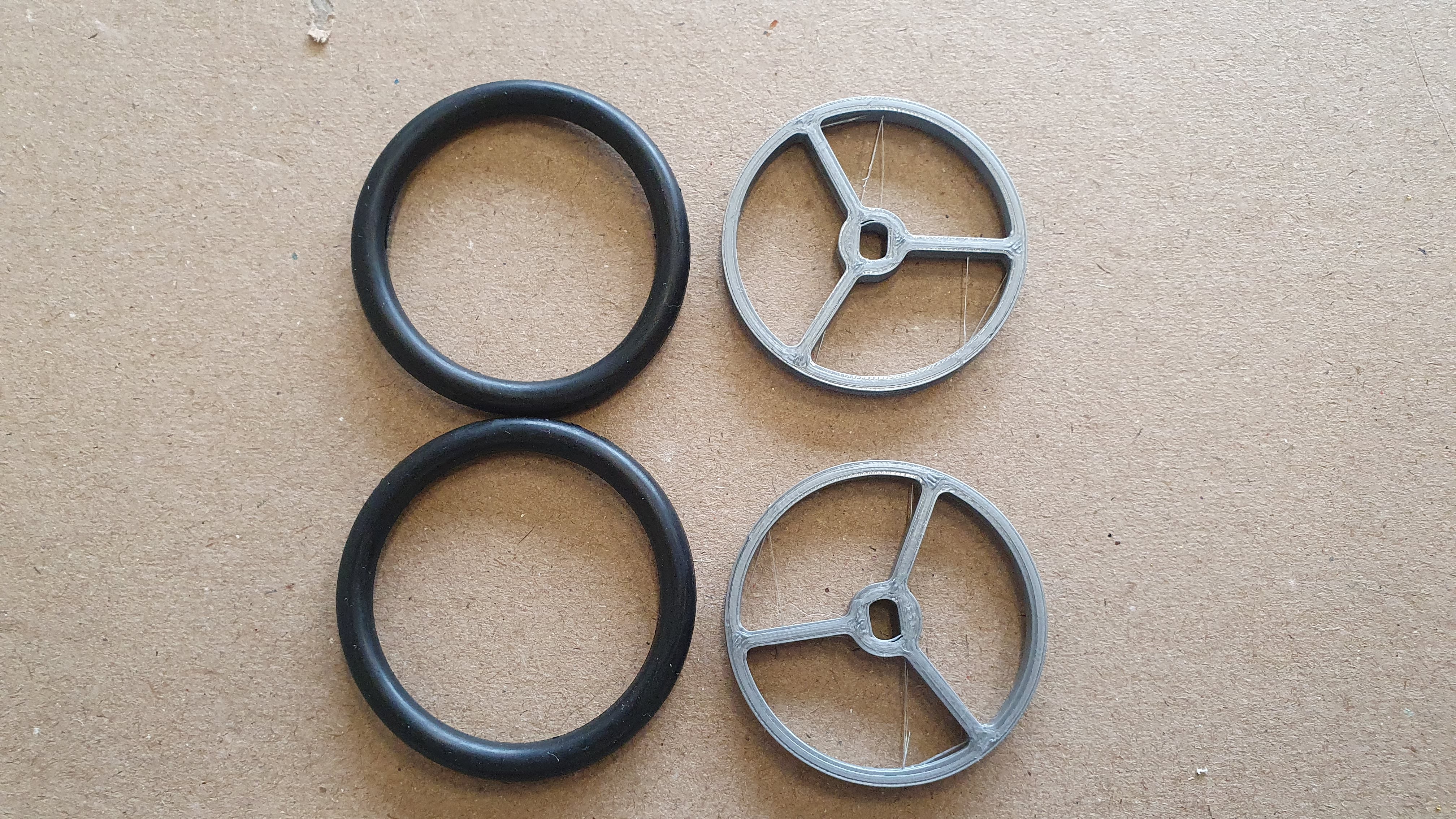
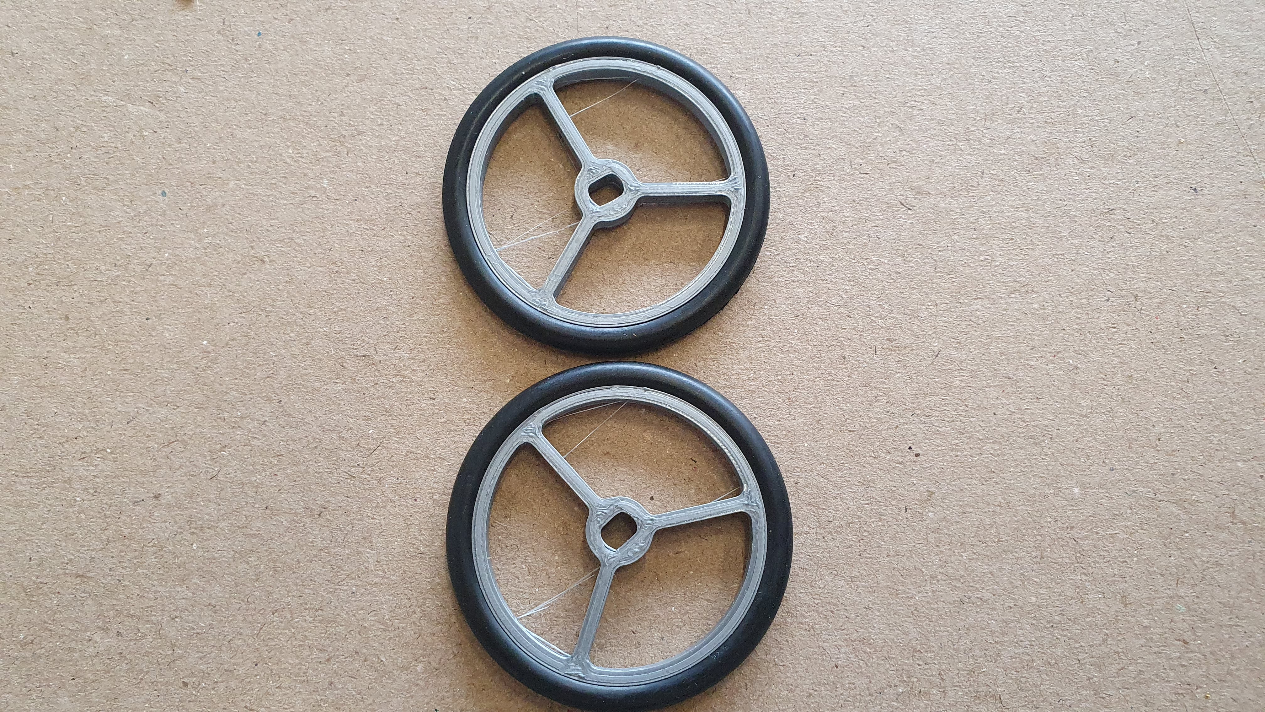
Wheels
Put the 50mm o-ring around the printed wheel
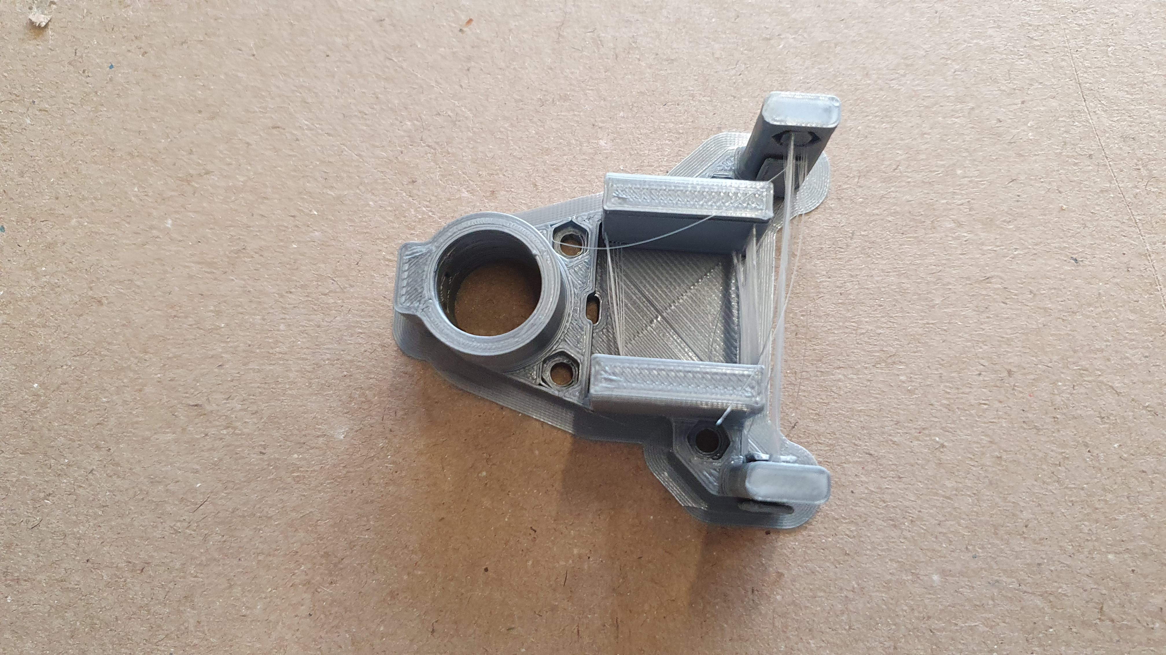
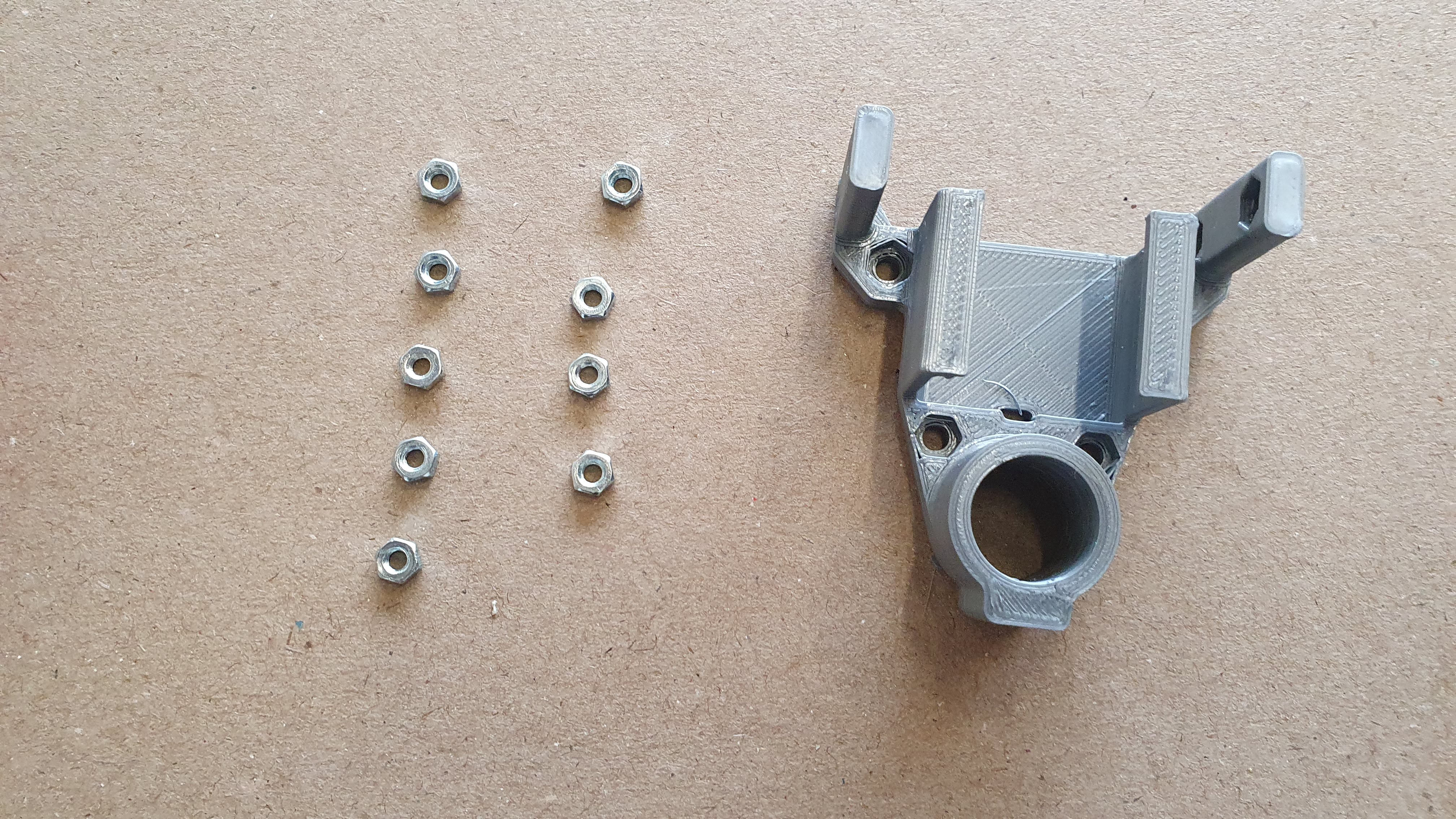
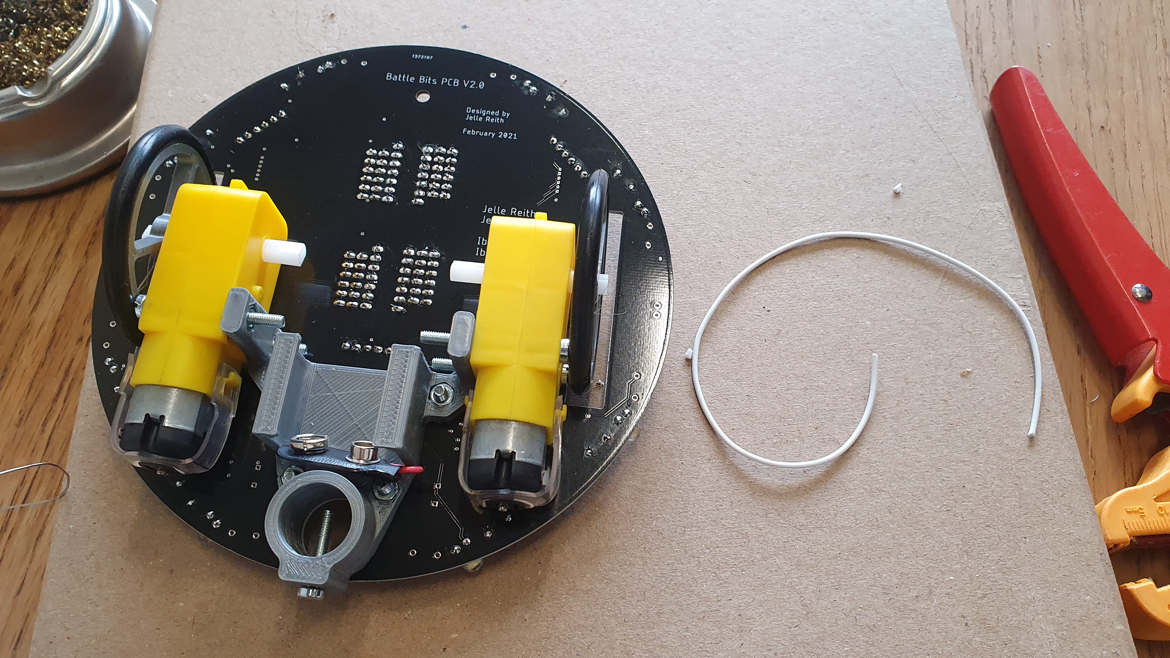
Wheel Base
Carefully remove all the 3d-print support material with the help of some needlenose pliers.
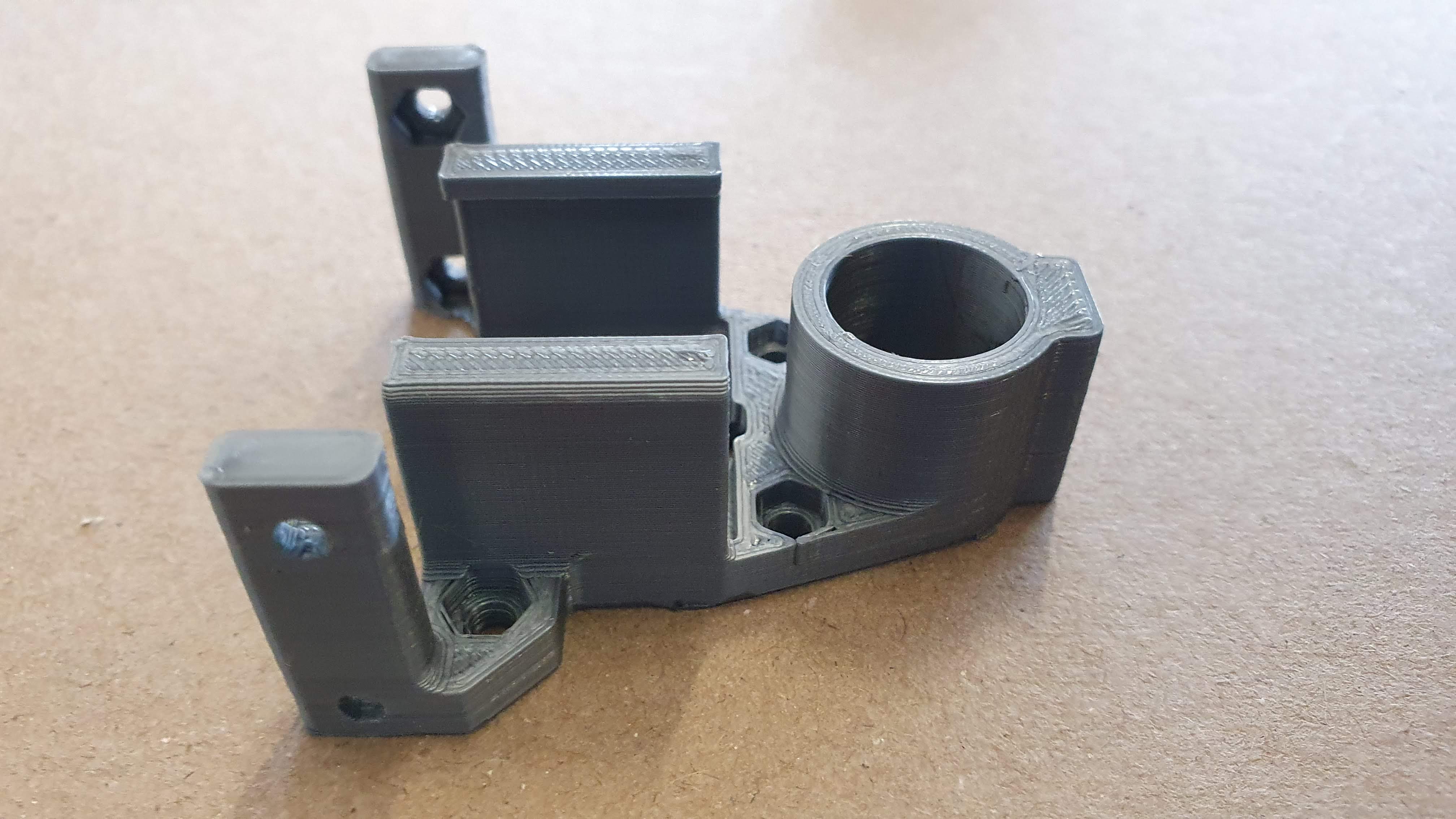
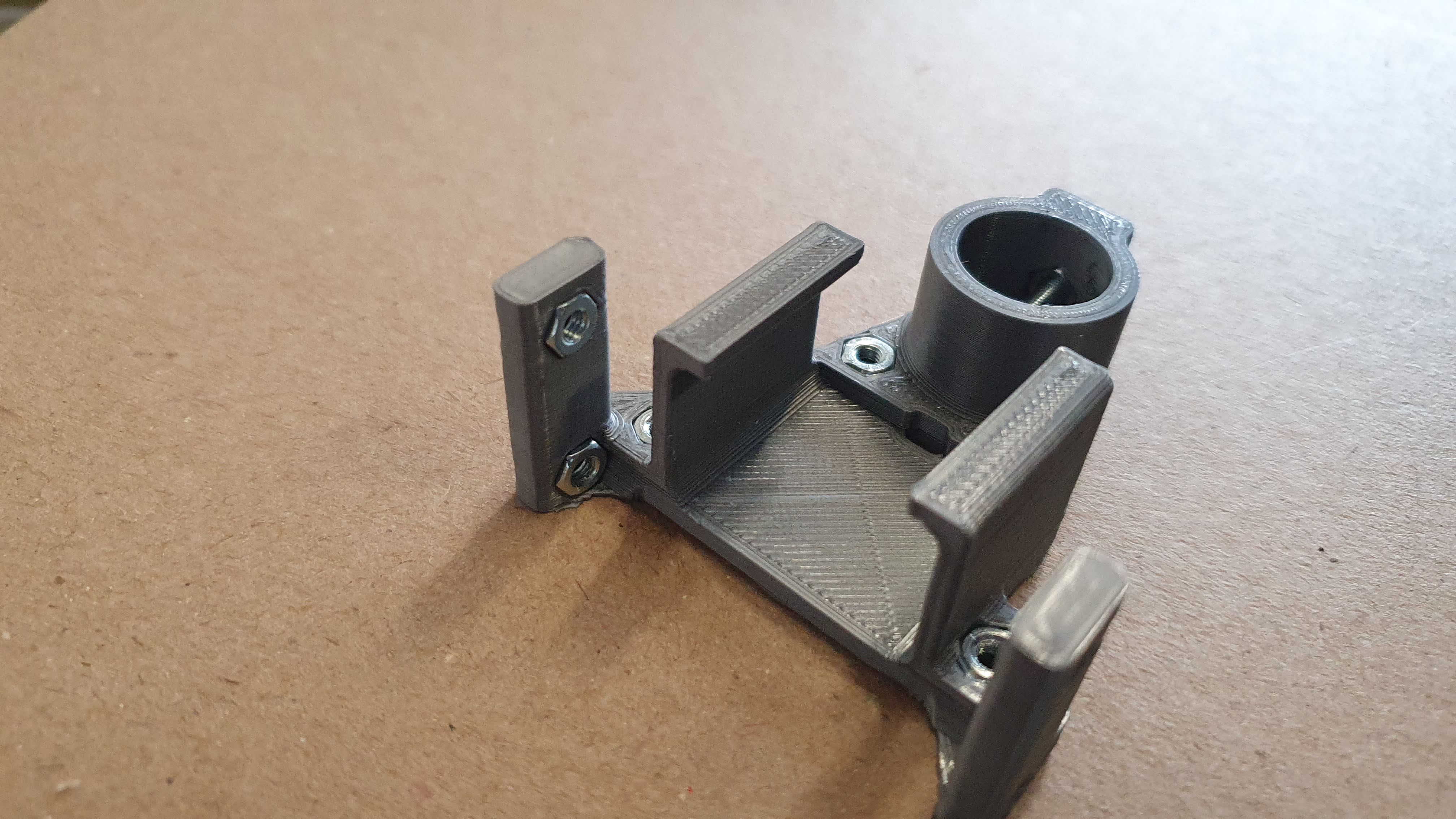
Place the 9 hex nuts in the corresponding holes of the wheel base:
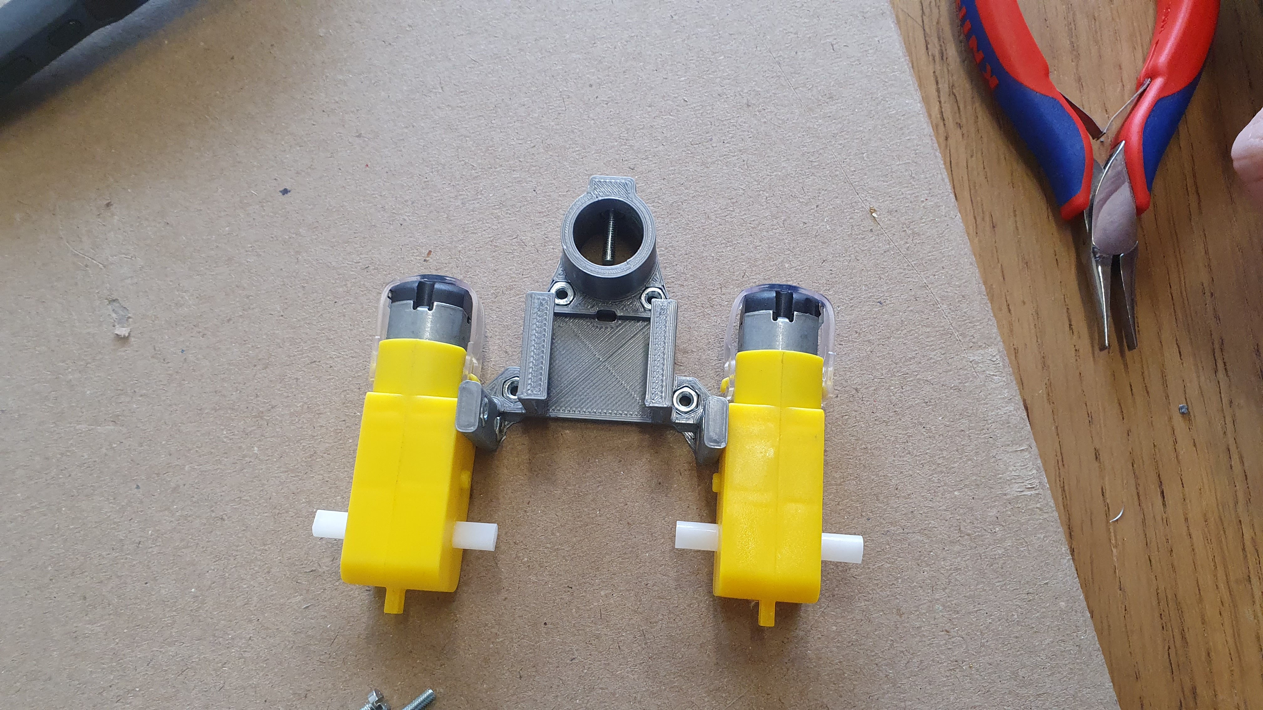
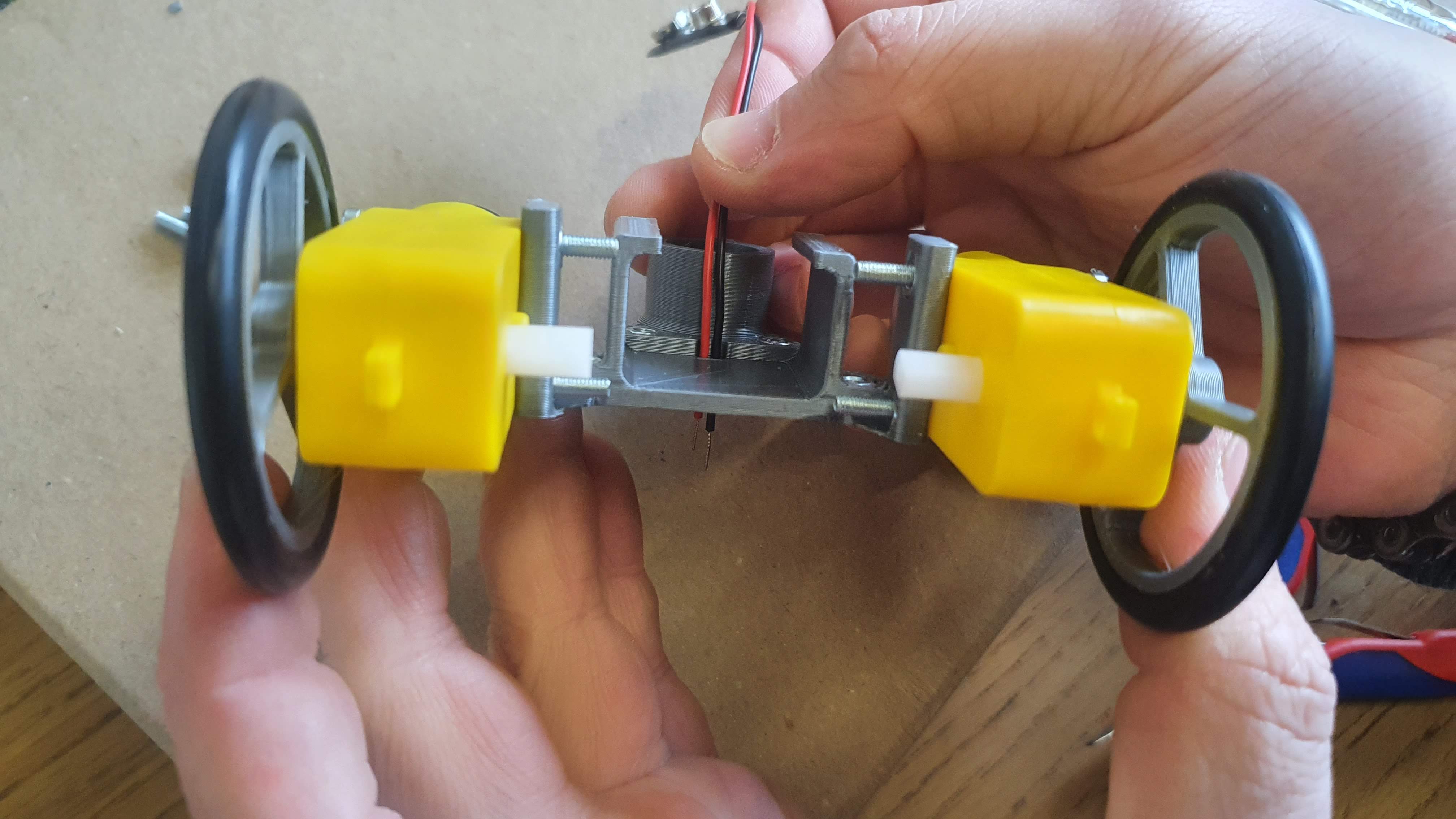
Place the motors and attach them with 30mm bolts. Make sure the motor leads are facing outwards
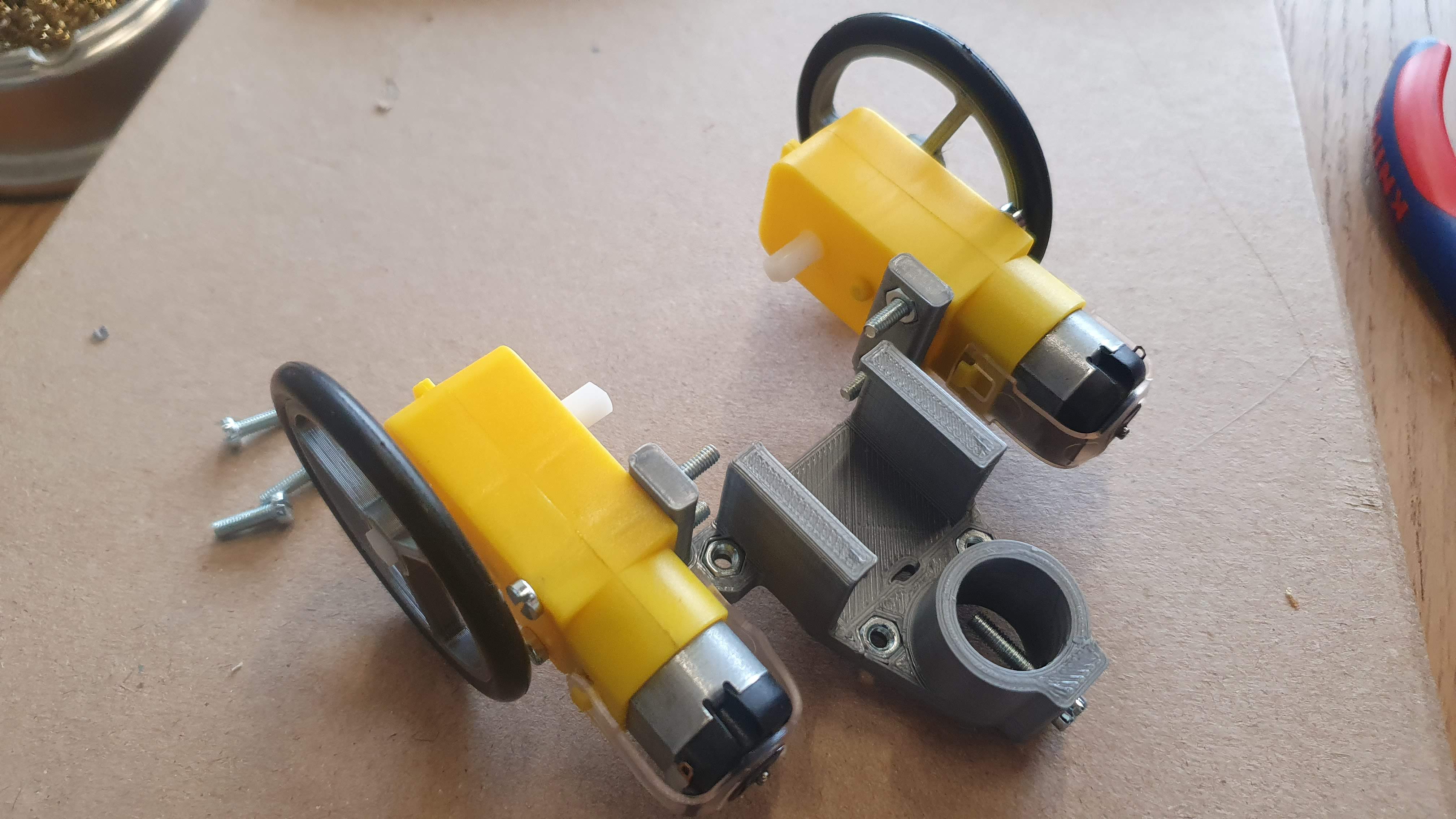
Push the wheels on to the motor shafts
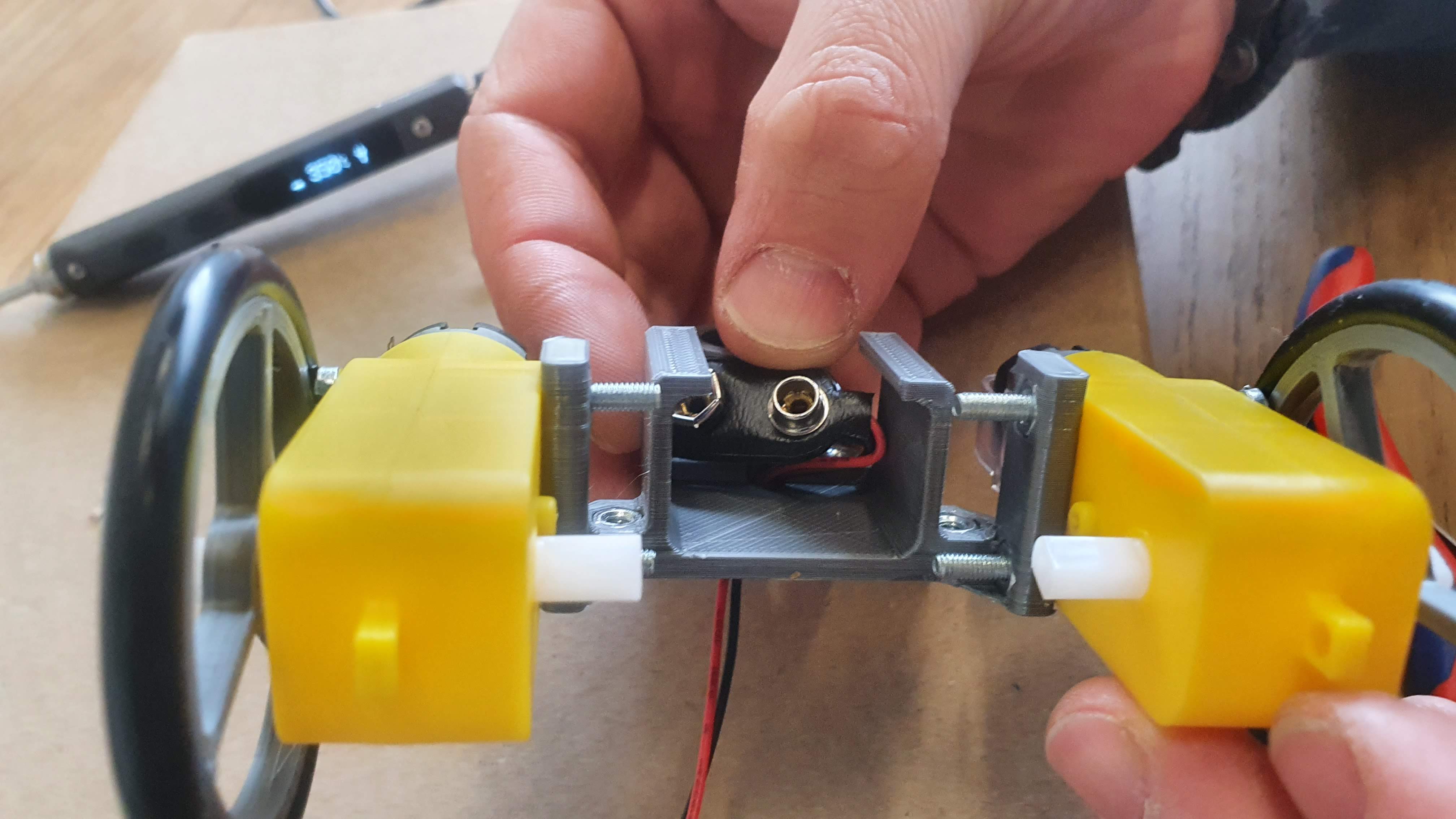
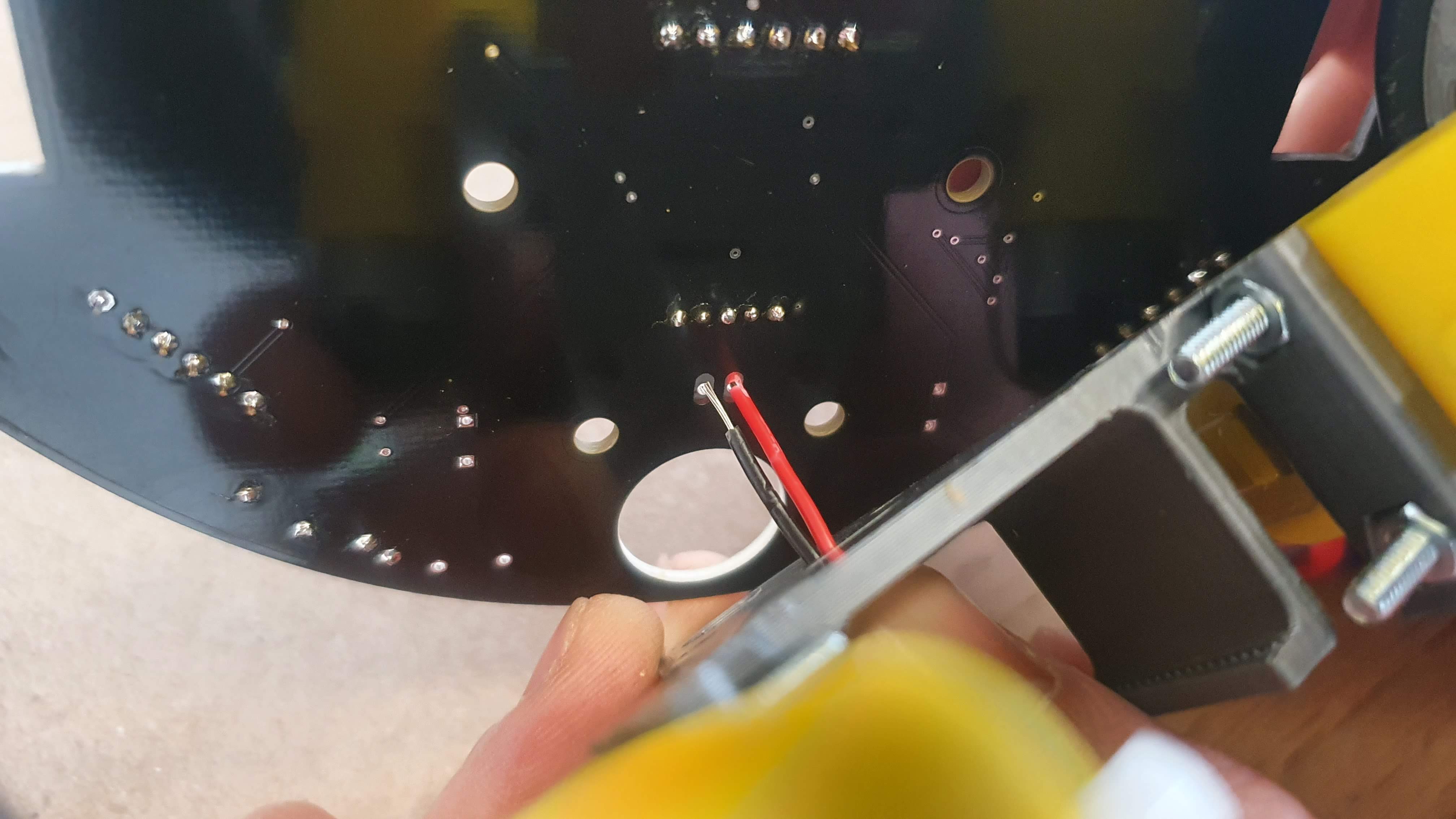
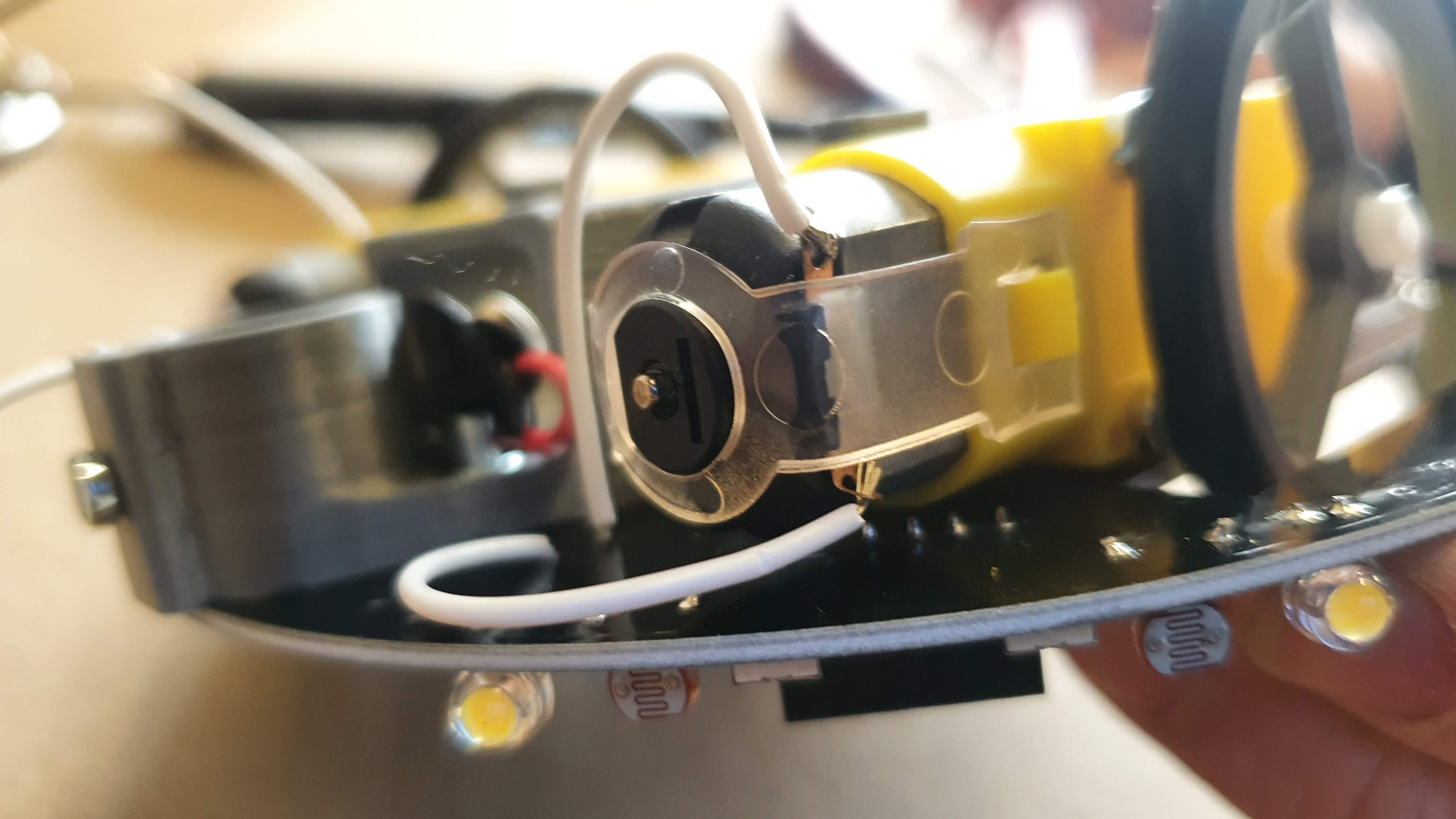
Push the 9v battery cable through the small hole. Make sure the red and black wire are as shown on the picture
 Bend the battery cable as shown in picture below.
Cut the cable so there is ~1cm left
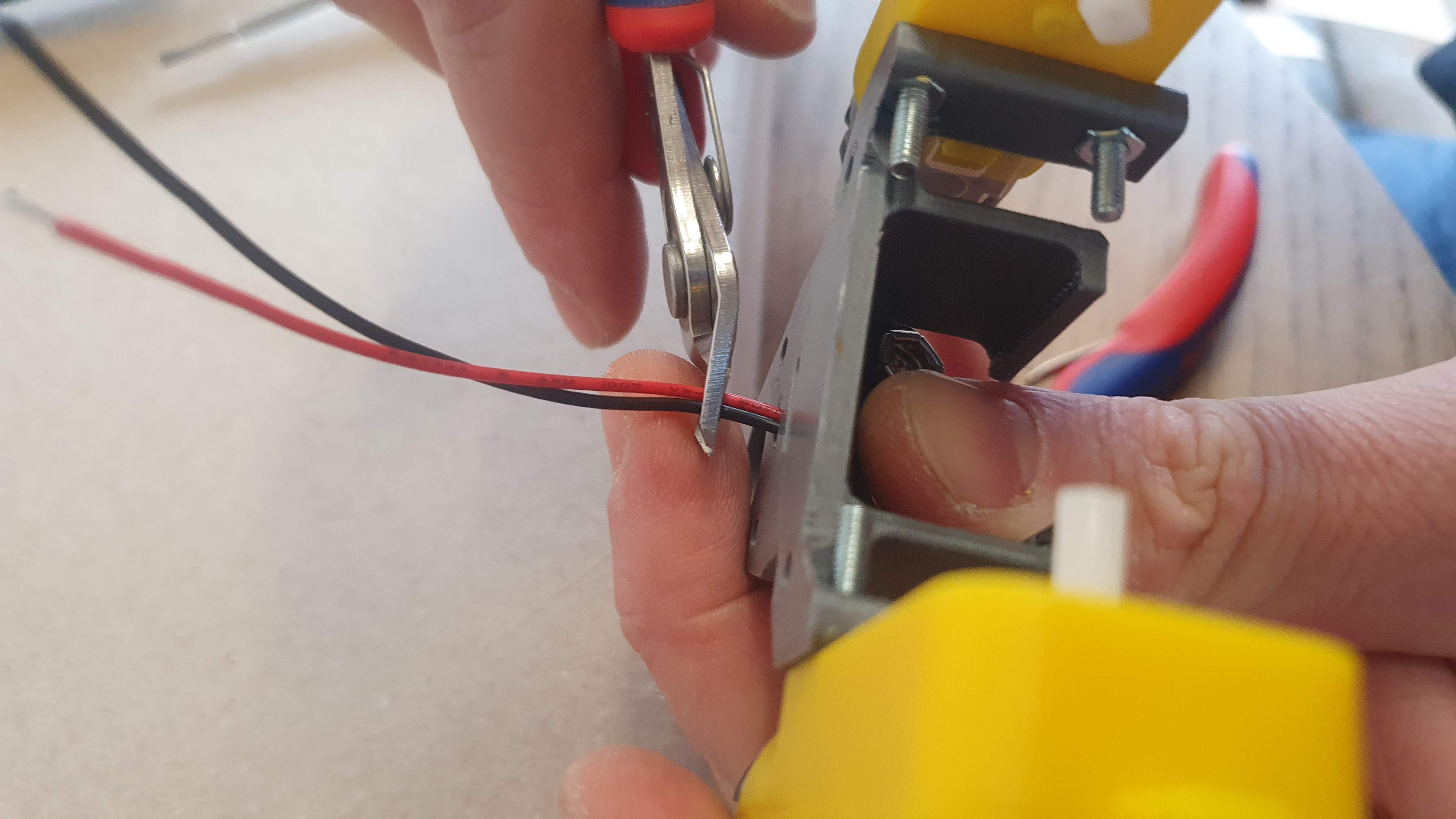
Strip the cables
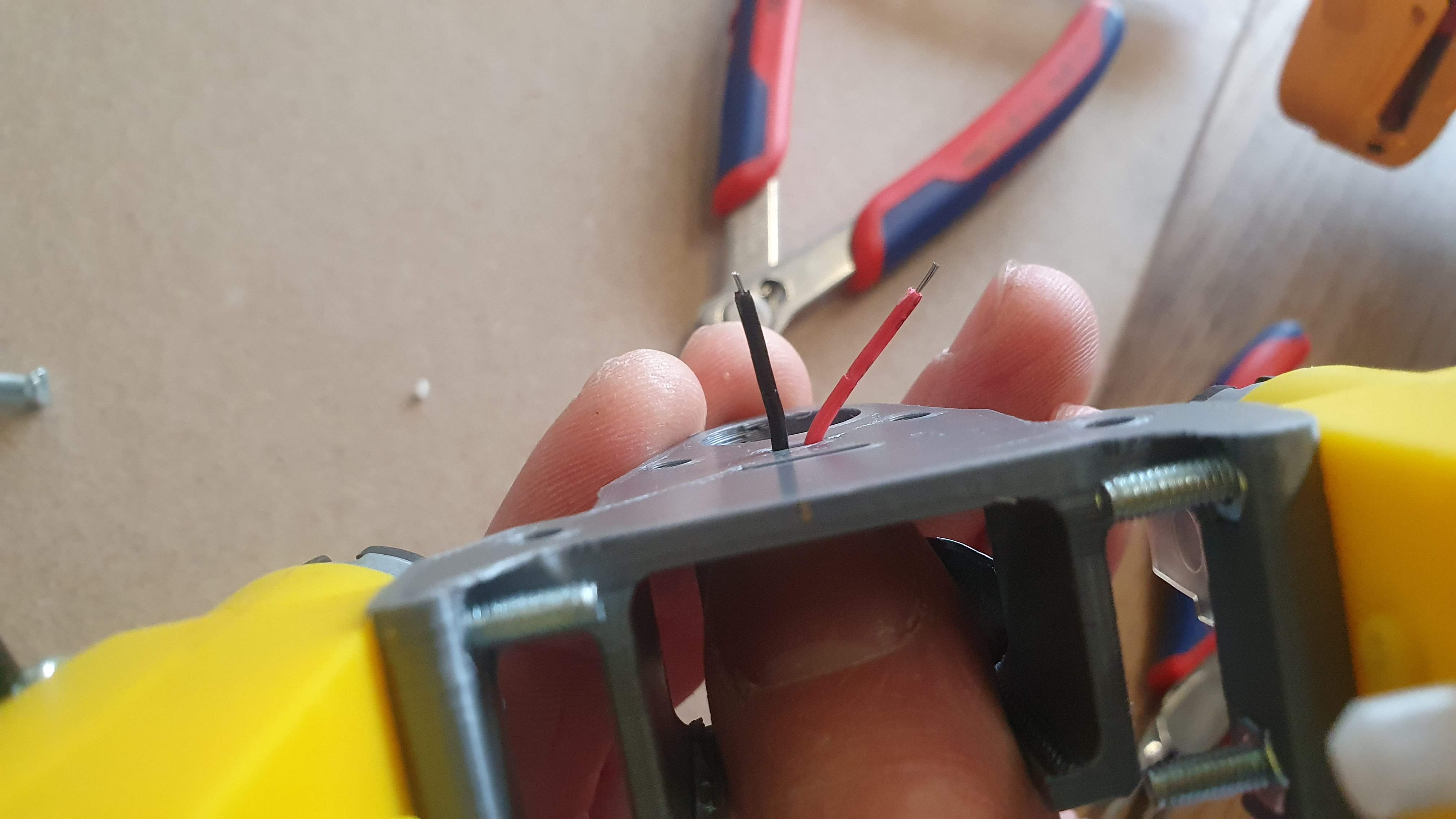
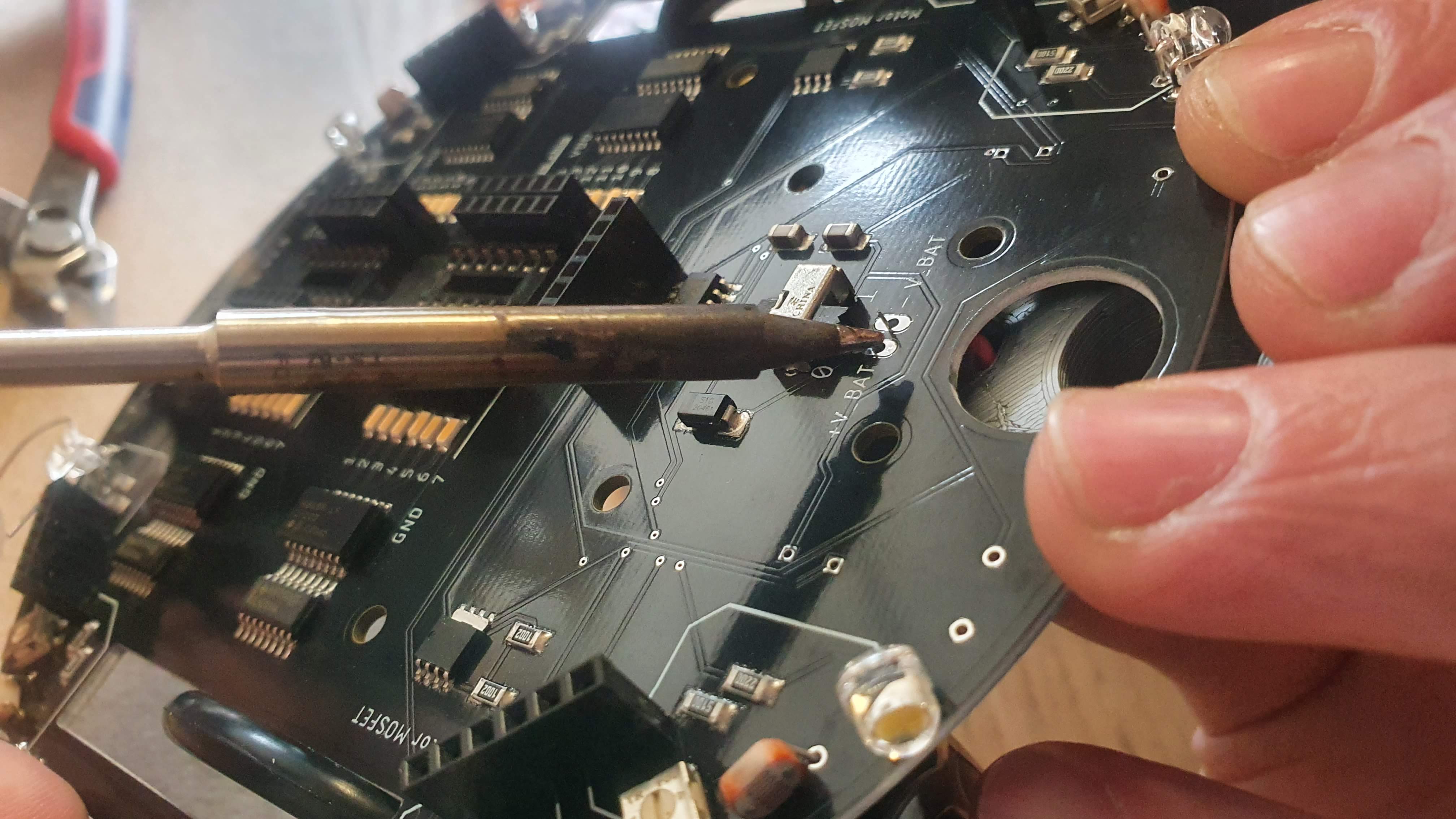
Push the cables trough the PCB as shown:
Solder the two cables.
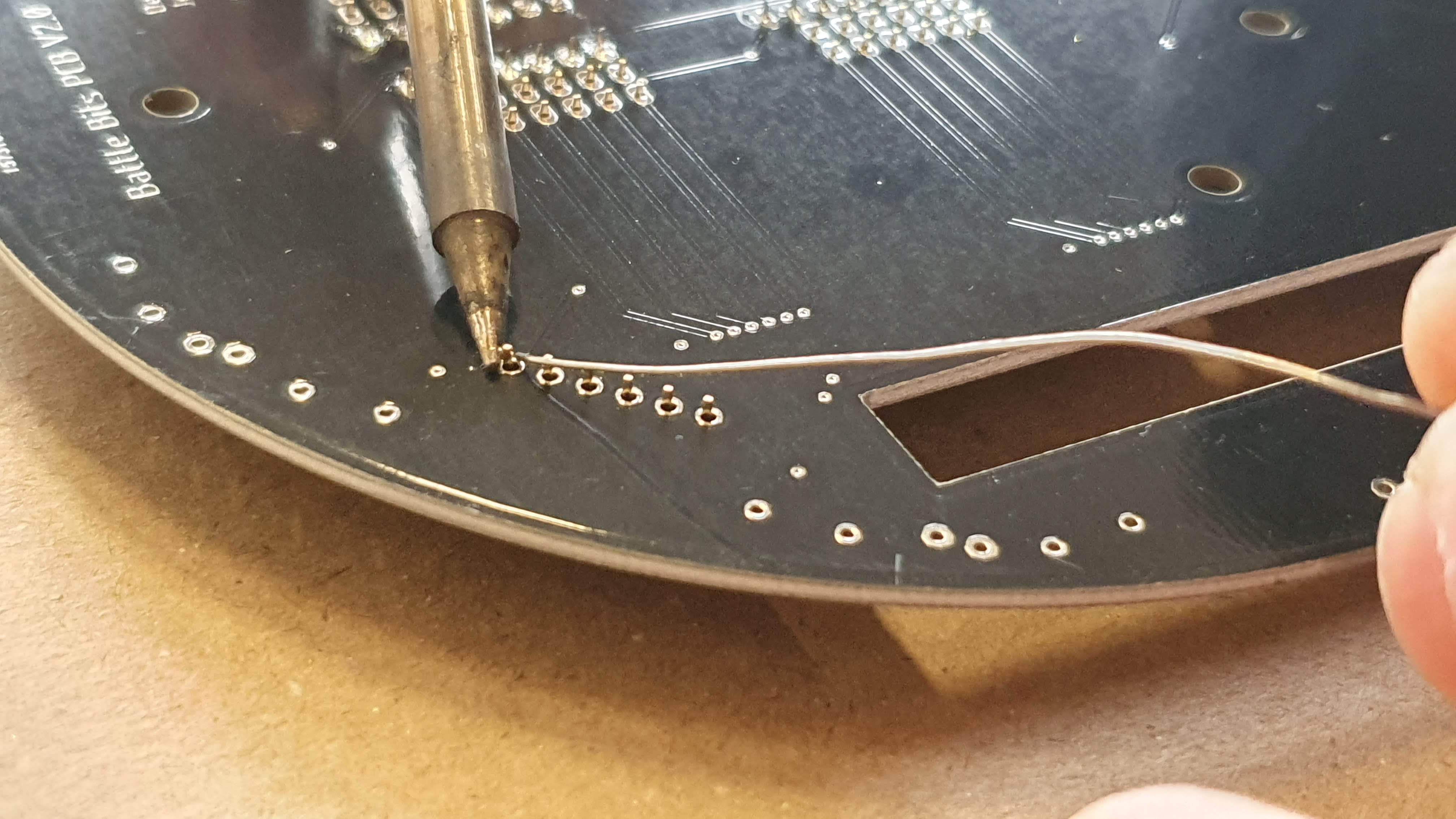
Take the white wire and cut in to four equal pieces:
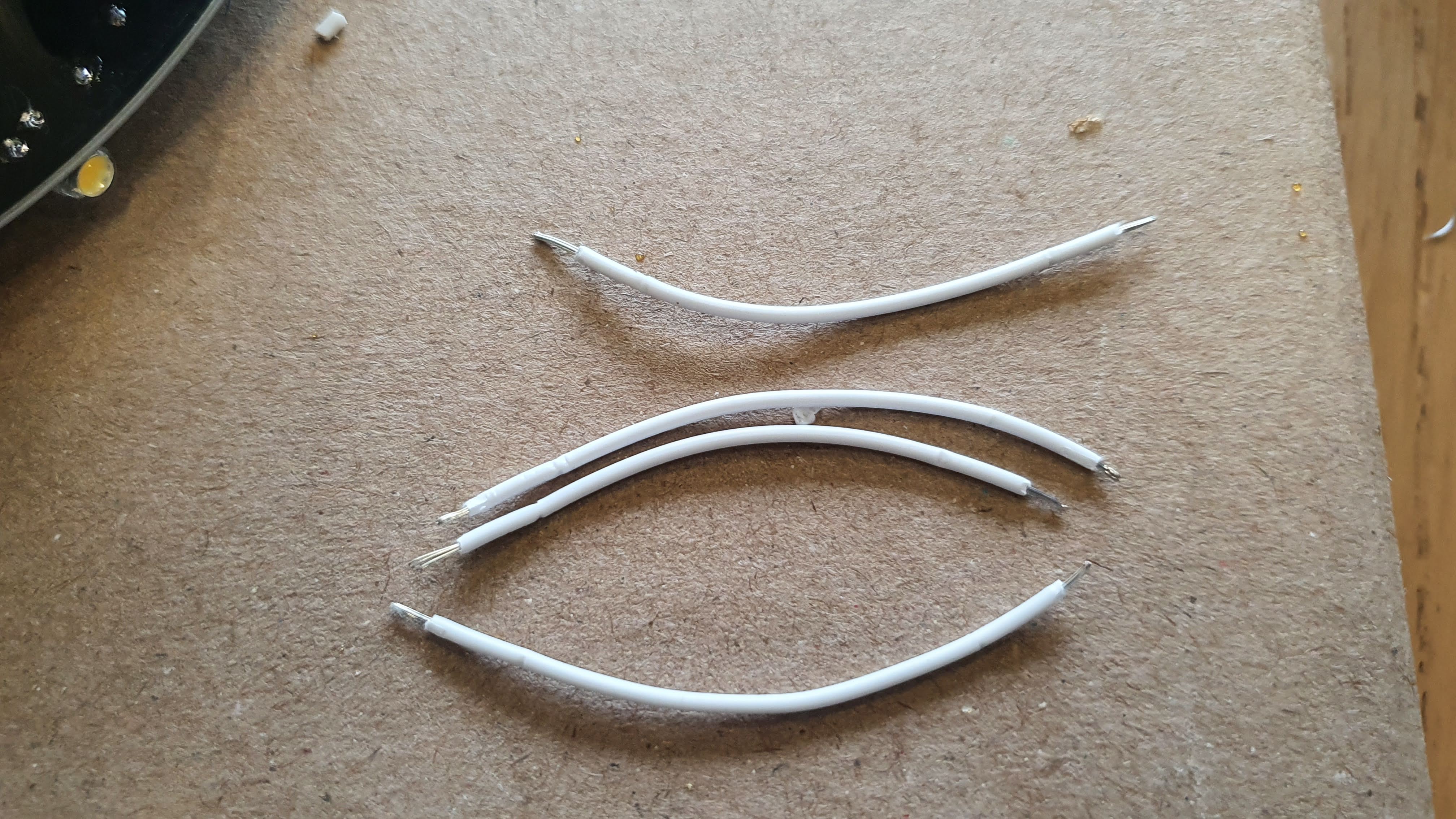
Use pliers to strip 2 mm of the wires and solder them as shown:
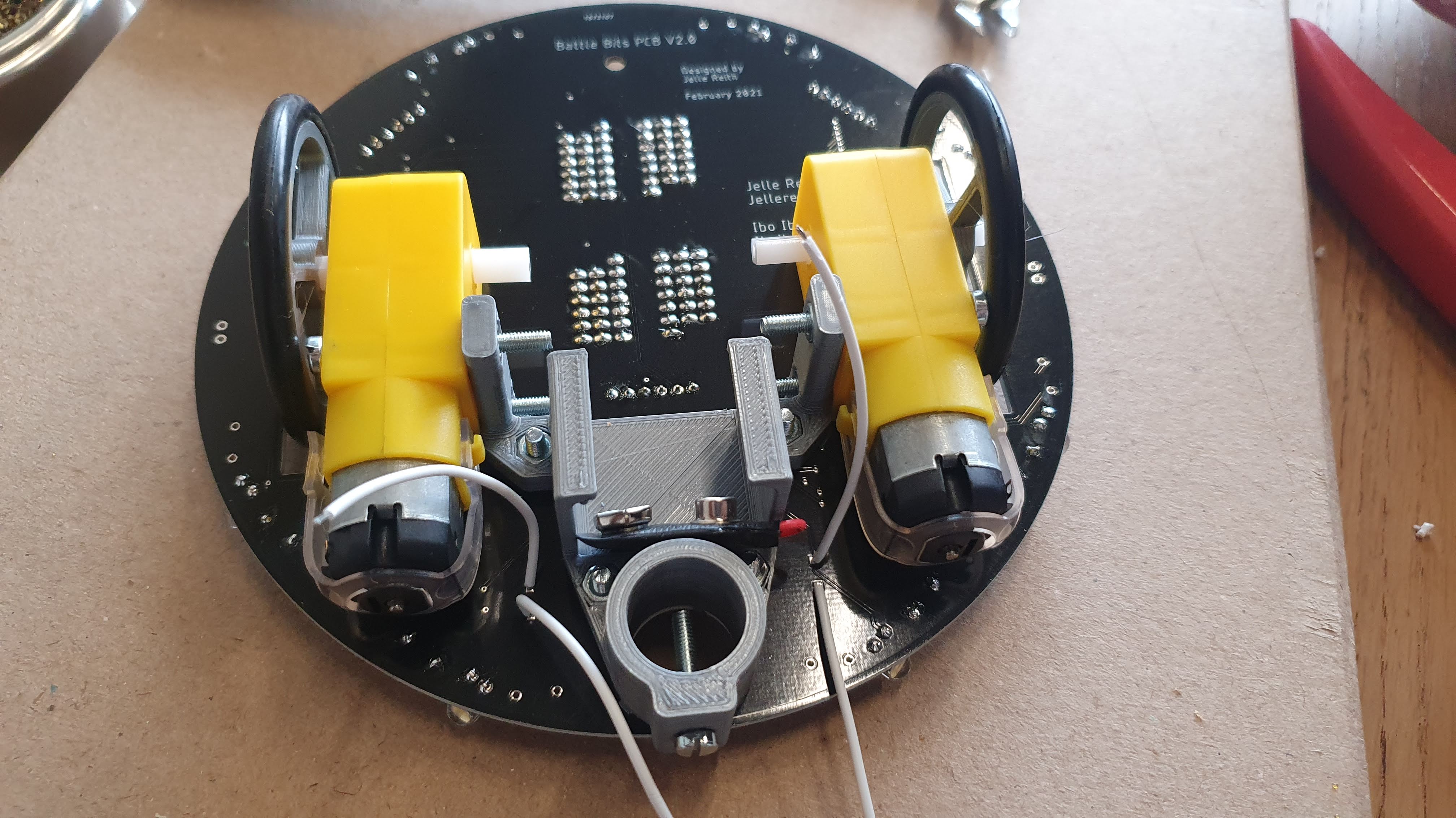
Solder to the motors as shown (wire closest to the edge at the bottom)
Placing the logic gates
- Ask Ibo or Jelle for 2 logic gates.
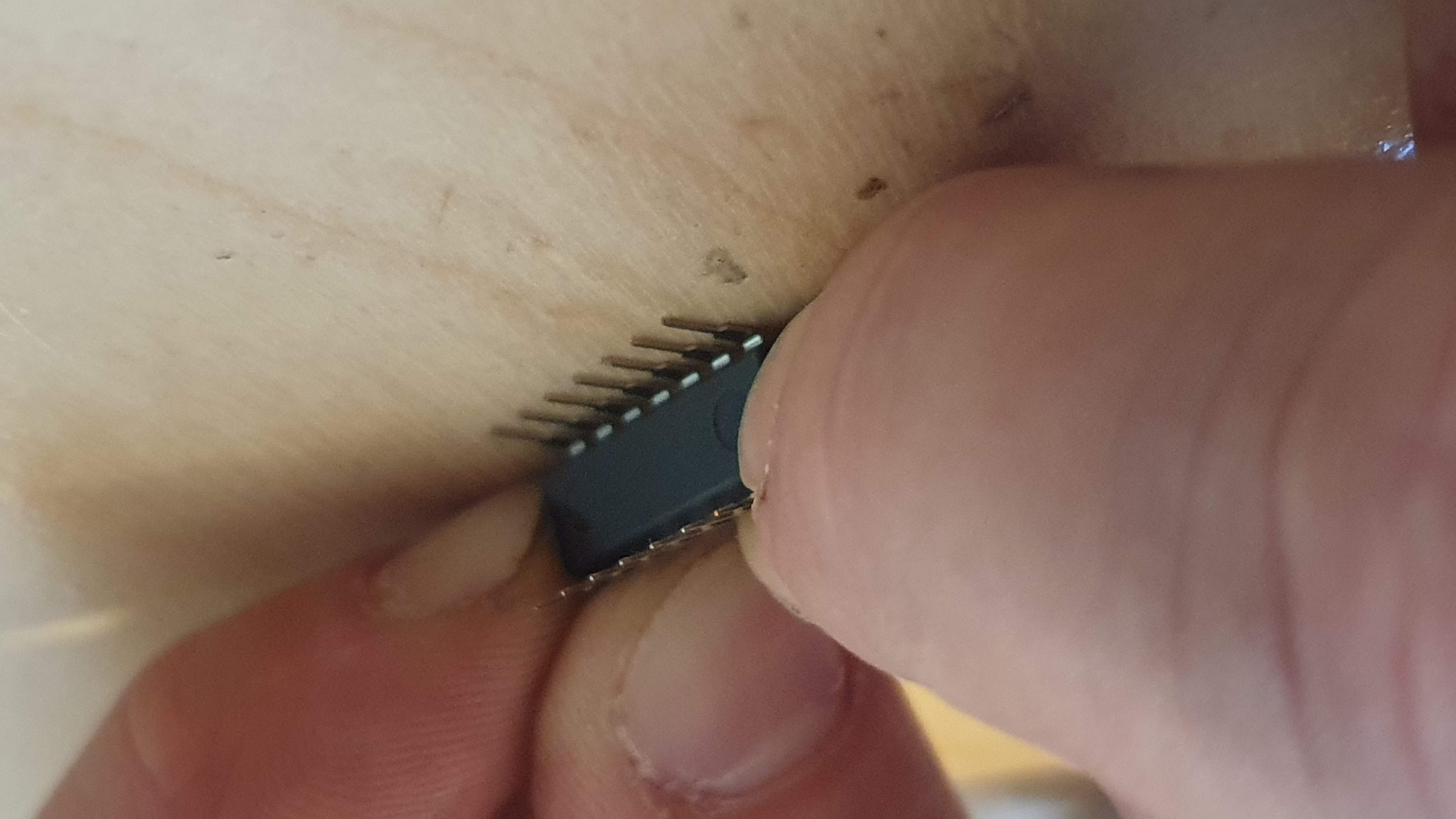
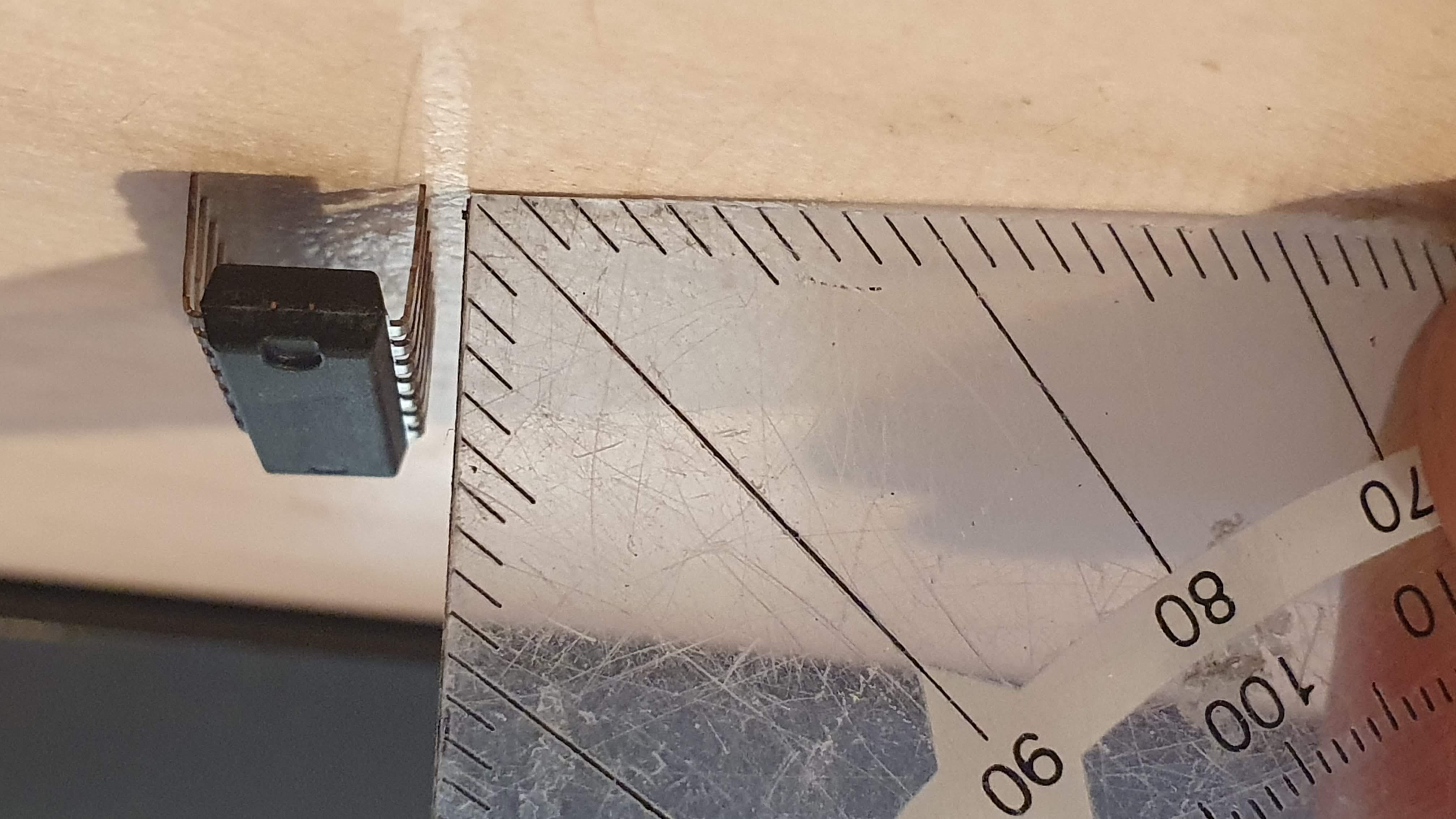
The pins of the logic gates are not at 90 degrees, so we have to bend them a little bit.
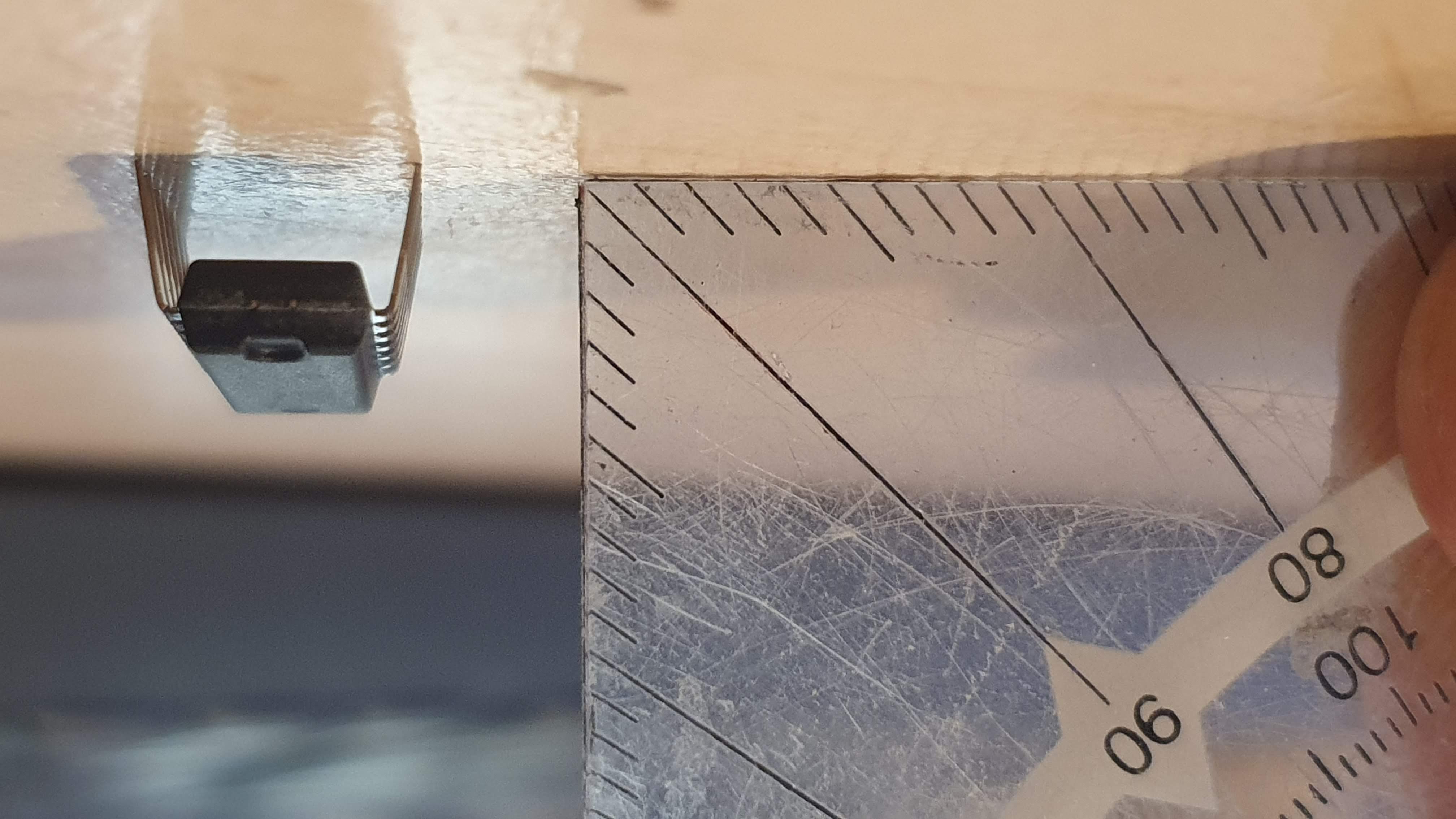
Use a flat surface to bend the legs of the logic gates in a 90 degree angle
Carefully push the logic gate into the socket. Make sure all legs are in the correct holes!
