7400 series logic gates and truth tables - ipibo/BattleBitsWorkshop GitHub Wiki
Logic gate IC's:
Although it is possible to make your own logic gates using basic components such as transistors and resistors it is usually easier and cheaper to uses dedicated IC's (integrated circuit). A integrated circuit is a semiconductor that is designed to perform a very specific function, for example a 555 timer IC is designed to generate a very stable oscillating signal with the help of some basic passive components like resistors and capacitors.
During this workshop we will work with logic gate ic's. The logic gates we will use all belong to the same family: the 7400 series. The 7400 family has a number of different sub-families, each sub-family with different characteristics (for example: 74HC for High-Speed CMOS (Complementary Metal Oxide Semiconductor) and 74LV for Low Voltage chips). For this workshop we will be working with the HCT sub-family (High Speed TTL (transistor-transistor logic)). Within the HCT sub-family we can make 4 groups:
- 6 channel NOT-gates (inverters)
- 4 channel 2 input gates
- 3 channel 3 input gates
- 2 channel 4 input gates
During this workshop we will be working with the 6 channel not gates and the 4 channel 2 input variants. Meaning that every IC (except for the 6 channel not gate) holds 4 logic gates, each with 2 inputs and one output.
4 channel 2 input gates pinout ATTENTION!!! THE NOR GATE HAS A DIFFERENT PINOUT!!!
![]()
-
Pin 1: GATE 1, INPUT X
-
Pin 2: GATE 1, INPUT Y
-
Pin 3: GATE 1, OUTPUT Z
-
Pin 4: GATE 2, INPUT X
-
Pin 5: GATE 2, INPUT Y
-
Pin 6: GATE 2, OUTPUT Z
-
Pin 7: VSS (ground)
-
Pin 8: GATE 3, INPUT X
-
Pin 9: GATE 3, INPUT Y
-
Pin 10: GATE 3, OUTPUT Z
-
Pin 11: GATE 4, INPUT X
-
Pin 12: GATE 4, INPUT Y
-
Pin 13: GATE 4, OUTPUT Z
-
Pin 14: VDD (+6v)
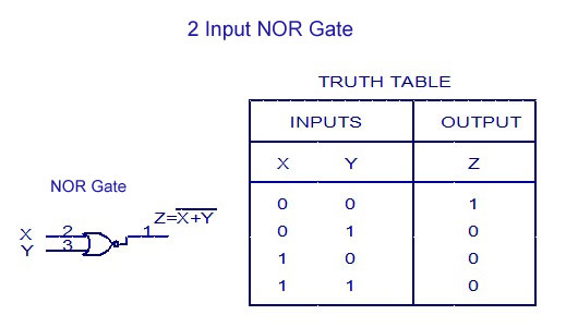
NOR GATE PINOUT!!!
![]()
-
Pin 1: GATE 1, OUTPUT Z
-
Pin 2: GATE 1, INPUT X
-
Pin 3: GATE 1, INPUT Y
-
Pin 4: GATE 2, OUTPUT Z
-
Pin 5: GATE 2, INPUT X
-
Pin 6: GATE 2, INPUT Y
-
Pin 7: VSS (ground)
-
Pin 8: GATE 3, OUTPUT Z
-
Pin 9: GATE 3, INPUT X
-
Pin 10: GATE 3, INPUT Y
-
Pin 11: GATE 4, OUTPUT Z
-
Pin 12: GATE 4, INPUT X
-
Pin 13: GATE 4, INPUT Y
-
Pin 14: VDD (+6v)
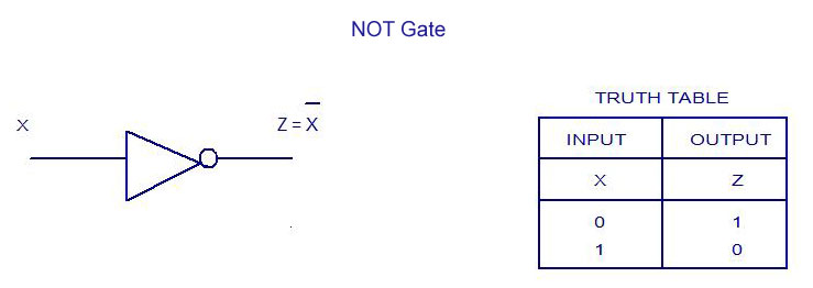
6 channel NOT-gates pinout!
![]()
-
Pin 1: GATE 1, INPUT X
-
Pin 2: GATE 1, OUTPUT Z
-
Pin 3: GATE 2, INPUT X
-
Pin 4: GATE 2, OUTPUT Z
-
Pin 5: GATE 3, INPUT X
-
Pin 6: GATE 3, OUTPUT Z
-
Pin 7: VSS (ground)
-
Pin 8: GATE 4, OUTPUT Z
-
Pin 9: GATE 4, INPUT X
-
Pin 10: GATE 5, OUTPUT Z
-
Pin 11: GATE 5, INPUT X
-
Pin 12: GATE 6, OUTPUT Z
-
Pin 13: GATE 6, INPUT X
-
Pin 14: VDD (+6v)
You can choose between the following IC's:
SN74HCT32N:
OR gate
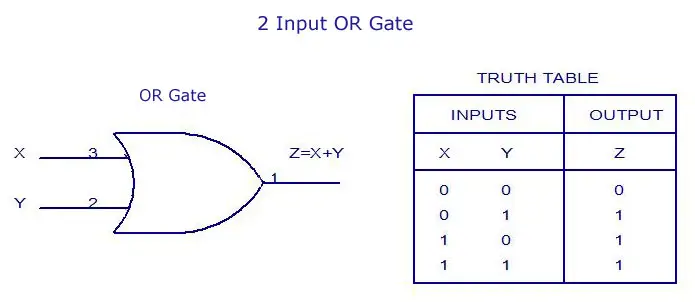
SN74HCT02N:
NOR gate
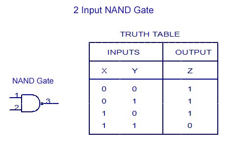
SN74HCT00N
NAND gate
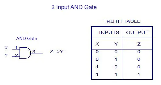
SN74HCT08N
AND gate
SN74HCT04N
NOT gate (inverter)
