Wiring - ilikecake/ESP32-Wall-Display GitHub Wiki
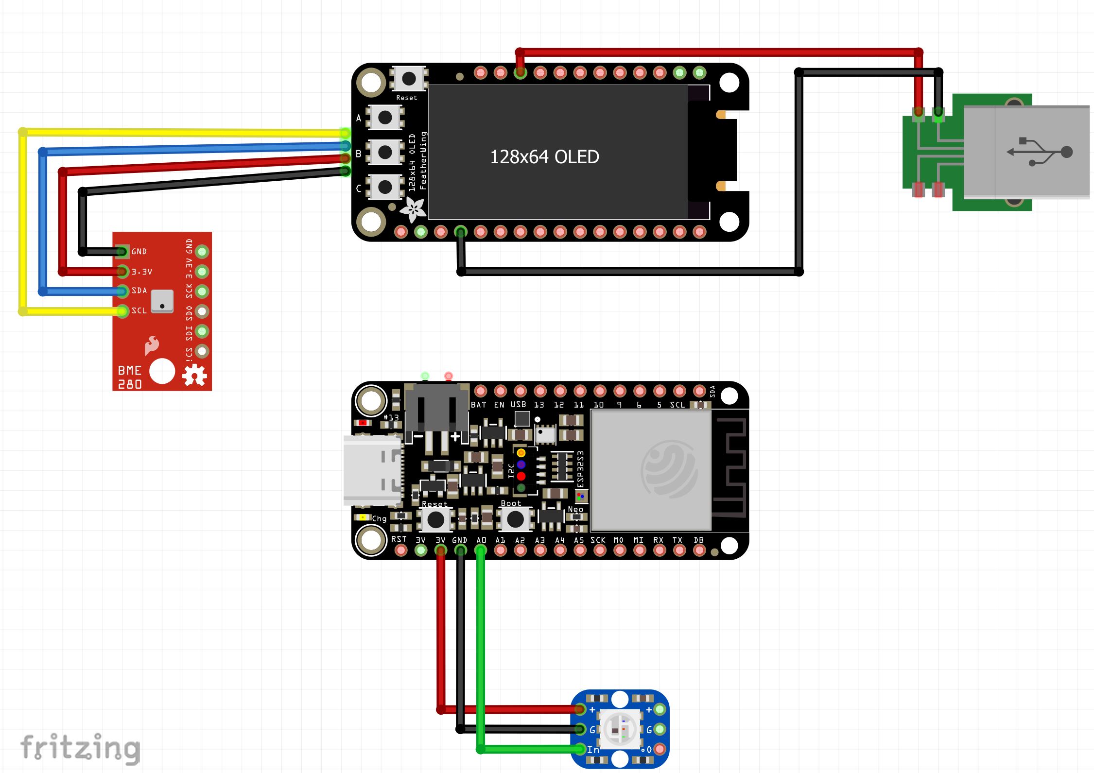
Start by soldering the headers onto the OLED and Feather. It does not really matter which gender header you use on which side, but in my case, I used male on the OLED and female on the Feather. Make sure when soldering the pins on the OLED that none of the pins stick past the surface of the glass on the OLED. It is pretty easy for the pins to move in the insulation, so make sure they are in the right place before soldering. A diagram of the rest of the wiring is shown below.
I used 30 gage wires for the USB power and Neopixel, and the Stemma QT wire for the connection to the BME280. I recommend partially assembling the device as you do the wiring in order to determine proper lengths for the wires. You don't want to end up with a lot of extra wire inside the case or you will have trouble finding a place for all of it.
I soldered power and ground wire from the USB PCB to pins on the OLED. You can also solder them to the matching pins on the Feather, but I did not have room to do that. The final wiring should look something like this:
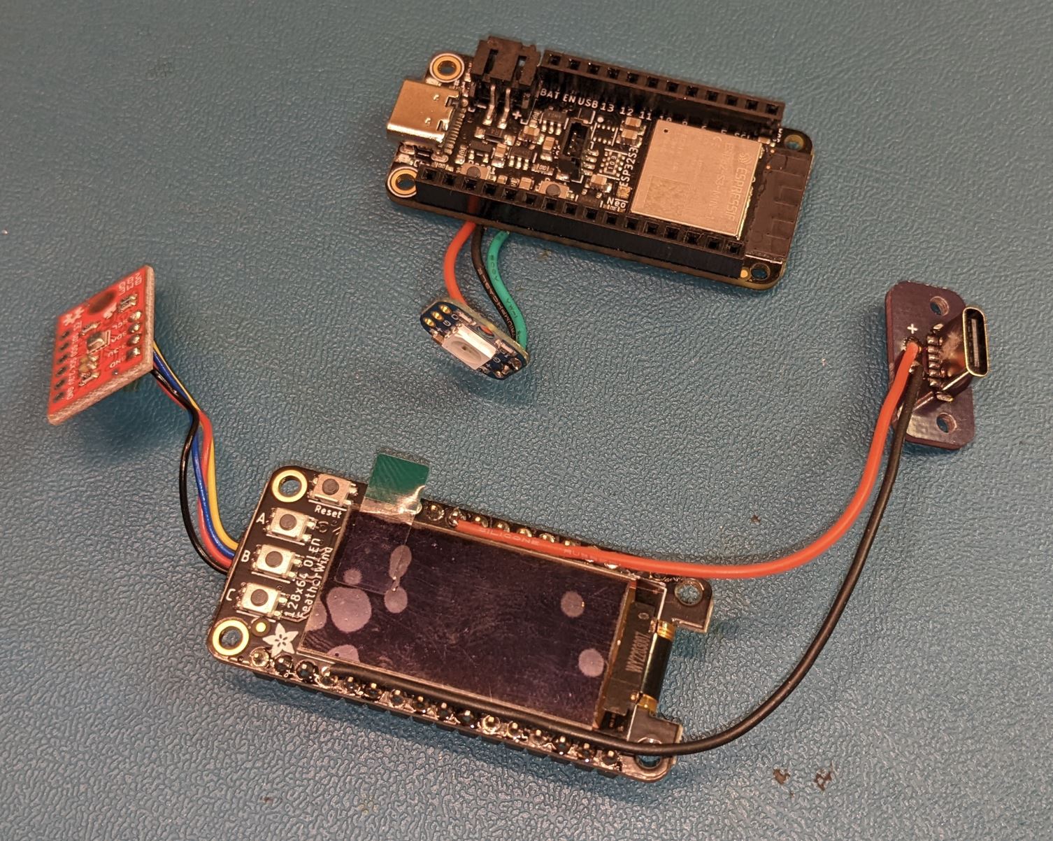
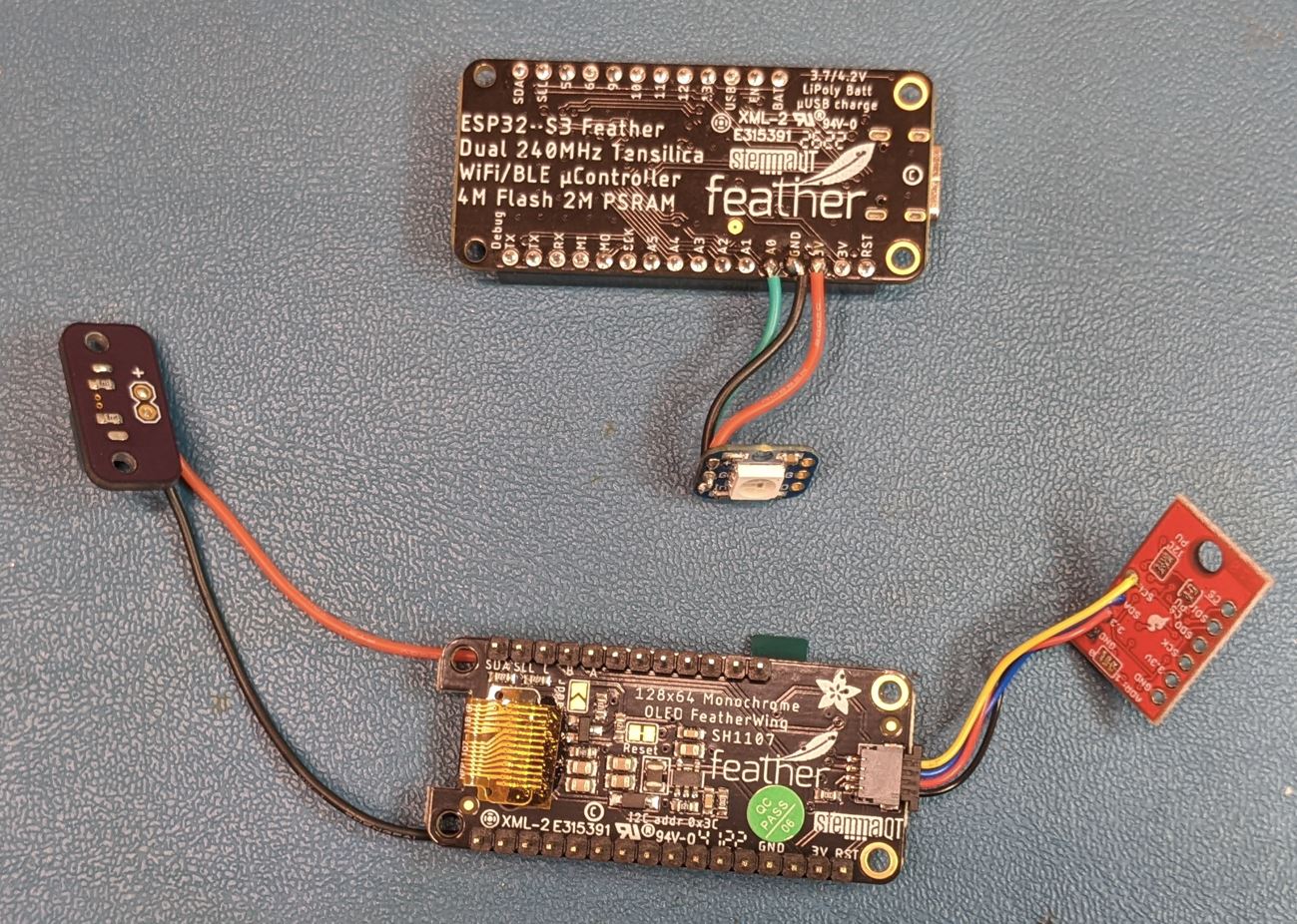
Approximate wire lengths are
- Power Entry: 3"
- BME280: 1"
- Neopixel: .75"
Note: you should avoid plugging in both the USB connector on the feather and the USB connector on the separate PCB. The separate PCB will only provide power, so you will need to use the USB port on the Feather for programming. Once everything is working, you can connect it over the USB power board.