Mechanical Design Guidelines - icub-tech-iit/cad-libraries GitHub Wiki
- CAD system
- Component coding
- CAD documentation standards
- Possible categories
- Materials
- Revision management
- Skin patches generation procedure
- Annotation feature creation procedure
- Tools creation procedure
- Production documentation
- Drawing conventions
- Robot assembly coding
- External Collaborations
The mechanical design and documentation of the projects of the iCub Facility shall be performed with Creo Parametric by PTC.
This section describes the mechanical CAD components coding standard for the iCub Facility projects. This coding scheme shall be used in all the design and development activities of the project as it is mandatory to maintain file traceability. The coding allows the definition of a unique alphanumeric code for each file produced in the design process from part files to assembly drawings. Proper coding is also mandatory to avoid issues with the department's ERP software (WinGST), which relies on the consistency of component coding. There are two types of items: custom components or assemblies and commercially available components. These two types of items require two types of coding that are described hereafter.
The total length of the code must never exceed 33 characters.
The code for commercial components is composed as follows:
AAA_BBB
where AAA is the producer name (eventually shortened) and BBB is the producer code.
Exceptions: Screws and fasteners, Misumi components, bearings.
Any spacing within the producer code BBB shall be replaced by a - (hyphen). If it contains a . (dot) or ( and ) (parenthesis), then it shall be replaced by an _ (underscore).
Example: M 2.5 should be M-2_5.
For standard commercial components and fasteners we use the ISO standard, when not available we use the DIN standard.
It is possible that the commercial code of the component to be codified is longer than the available part code characters (limited to 34 in Creo Parametric). In this case, there are two options:
- The last four characters of the part code are replaced by
_VCC, where CC is a two-digit number indicating a specific variant of a given product.- example:
faulhaber_2224u024sr_22ekv_v01
- example:
- We use a short name for the manufacturer.
- List of shorted manufacturers:
- Harmonic Drive ->
H-DRIVE
- Harmonic Drive ->
- List of shorted manufacturers:
Further information regarding the product code shall be integrated into the part description, and/or within the ERP/PLM software being used for the production of components.
All custom components and assemblies shall be coded as follows:
AAA_BBB_CC_DDD_EEE
where:
-
AAAis a short (5 letters or less) acronym describing the project -
BBBis an incremental number identifying the main assembly to which the part or assembly belongs -
CCis a type identifier (that explains what the file is) -
DDDis an incremental part or assembly group identification number -
EEEis an optional string that is used to help identify main assemblies (see below).
Some currently used project codes are:
ICUB3CERECUB
Furthermore specific identifiers are used for the following special cases:
-
IC- Commons coding
The commons coding shall be employed in the cases in which parts can be used on multiple projects (e.g. force-torque sensors, some electronic assemblies, and the iCub heads). In these cases, the component is common to multiple projects hence shall be codified with the commons coding style. The commons coding prefix is IC. -
IG- Gadgets coding
Some parts and assemblies are optional add-ons for the robot and, as such, are not placed inside the full-featured robot assembly. These components are referred to as "gadgets" and are coded with the IG prefix. -
IT- Tools coding
These are custom parts and assemblies that help mount and dismount robot components, test or debug solutions as a setup, prepare or mechanically transform other parts. They are not typically part of the robot assembly and should not be accounted for in the BOM. See the dedicated section to learn the tools creation procedure.
The active codes and assemblies are listed on the main assemblies list page. Whenever a new project or setup is issued the code shall be added to the projects/setups list.
Currently used type identifiers (CC part of the code) are:
-
Pfor parts -
mfor mirror parts (TBD) -
Gfor sub-assemblies -
Afor top-level assemblies -
Rfor reworked components (see section) -
SKfor skeleton model
These last characters are occasionally used mainly to quickly identify the main robot sub-assemblies. They are useful but not mandatory and should be used only for really high-level functional sub-assemblies (head, lower body, upper body...).
Component codes shall be unique. Assigning the same code to a part and to an assembly, although possible within the Creo Parametric workflow shall never be done, as this creates failures when transferring the BOM to the ERP software.
This section presents the set of rules to be followed for the right definition of CAD files. The proper definition of CAD files is of the utmost importance for the production phase of the robot. Indeed, the production phase of the robot is partially automatic and automatic processes heavily rely on the correct definition of part and assembly information.
Each 3D model file contains a series of additional data besides the geometric information. The additional data are stored in the default start parts, and are inherited automatically every time a new part or assembly is created from these:
- start part
- start assembly
- sheetmetal start part
- reworked start part
- ECAD start part
- start part commercial.
The standard parts contain views, mass properties settings, and default parameters settings.
Sheet metal components need a start part on their own because they require a metal carpentry technological process, that is completely different from CNC and 3D printed components processes (material removal or additive printing techniques).
The complete list of parameters of the start parts is listed in the following table (some start parts have fewer parameters).
| Symbolic constant | Default value | Type | Comments |
|---|---|---|---|
| TIPO | XXXX | String | Category of the part (see section) |
| DESIGNED | XXX | String | Acronym of the group designing the part |
| DRAWN | XXXXXXXXX | String | The name of the designer |
| TREATMENT | - | String | The treatment (if any) to be applied to the part |
| REV | 0 | String | Revision of the part (alphanumeric: A1, A2, A3, …) |
| DESCRIPTION | XXXXXXXXXXXXXXXXX | String | Informative description of the part |
| MATERIAL | ERGAL70 | String | The material assigned to the part. |
| DENOMINAZIONE | XXXXXXXXXXXXXXXXX | String | Additional parameter maintained for backward compatibility |
| SUB_DESCRIPTION | String | (optional) sub-description of the part | |
| TOL_DIM_CLASS | m | String | Dimensional tolerance class |
| TOL_GEOM_CLASS | K | String | Geometric tolerance class |
The DENOMINAZIONE and MATERIAL parameters are compiled automatically by CreoParametric and are filled by the system at the first regeneration of the part.
The material of the start part is set to ERGAL70. Standard materials can be loaded from the material library folder.
Note: The part description and revision fields will be used for the preparation of the project BOM. It is of the utmost importance that the fields are filled properly and with meaningful content.
The DESCRIPTION parameter shall be compiled as described in section 2.1 of the NASA GSFC X-673-64-1F, ENGINEERING DRAWING STANDARDS MANUAL.
Prescriptions are as follows:
Drawing Title
General information for the selection or development of a drawing title is as
follows:
a. The title should be as brief as possible but should contain sufficient information to categorize the part properly and to distinguish it from other similar parts.
b. The drawing title shall consist of the following:
1. Identifying a noun or a noun phrase.
2. The most significant modifier or modifying phrase.
3. The next most significant modifier or modifying phrase.
The noun or noun phrase establishes a basic concept of an item. The modifiers serve to narrow the area of concept established by the basic name. A modifier is separated from the noun or noun phrase by a comma and from any preceding modifier by a comma. The type designator and/or any additional modifiers required to further identify an item are separated from the first part of the title by a dash. Where applicable, the word “ASSEMBLY” shall be used as the last word of the noun phrase.
EXAMPLES:
“Beam, Hoisting, Guided Missile”
“Cover, Protective, Rocket Motor—Forward Section”
“Cabinet, Electrical Equipment—CY-147”
“Transportation—Dolly Assembly, Earth Satellite”
c. The noun, or noun phrase, is never abbreviated. Abbreviations are used in the modifiers only when space is limited. [...]
d. When one drawing supersedes another, the new drawing, when practical, has the same title.
e. Parentheses are not used to enclose any portion of the drawing title.
[...]
For filling the dimensional and geometric tolerance classes parameters refer to the "General ISO Geometrical Tolerances" standard ISO 2768.
The dimensional tolerance classes for linear dimensions are reported for reference in the following table.
| f (fine) | m (medium) | c (coarse) | v (very coarse) | |
|---|---|---|---|---|
| 0.5 up to 3 | ±0.05 | ±0.1 | ±0.2 | - |
| >3 up to 6 | ±0.05 | ±0.1 | ±0.3 | ±0.5 |
| >6 up to 30 | ±0.1 | ±0.2 | ±0.5 | ±1.0 |
| >30 up to 120 | ±0.15 | ±0.3 | ±0.8 | ±1.5 |
| >120 up to 400 | ±0.2 | ±0.5 | ±1.2 | ±2.5 |
| >400 up to 1000 | ±0.3 | ±0.8 | ±2.0 | ±4.0 |
| >1000 up to 2000 | ±0.5 | ±1.2 | ±3.0 | ±6.0 |
| >2000 up to 4000 | - | ±2.0 | ±4.0 | ±8.0 |
Permissible deviations in mm for ranges in nominal lengths for tolerance class designators.
Note: these values shall be written in lower case.
| H | K | L | |
|---|---|---|---|
| <= 10 | 0.02 | 0.05 | 0.1 |
| >10 up to 30 | 0.05 | 0.1 | 0.2 |
| >30 up to 100 | 0.1 | 0.2 | 0.4 |
| >100 up to 300 | 0.2 | 0.4 | 0.8 |
| >300 up to 1000 | 0.3 | 0.6 | 1.2 |
| >1000 up to 3000 | 0.4 | 0.8 | 1.6 |
Note: these values shall be written in the UPPER case.
The commercial components must be imported (or designed) using the dedicated start part start_part_commercial.prt.
In this part, we must fill the parameters DESIGNED, DRAWN, DESCRIPTION and TIPO. Refer to the section Standard parts for a description.
For commercial parts the mass properties are defined by adopting the following procedure:
-
take the mass from the datasheet
-
compute the volume of the Creo part
-
calculate an
average densityas mass/volume -
if necessary, remove all the materials assigned to the part
-
assign the
average densityto the materialPTC_SYSTEM_MTRL_PROPS
-
check that the mass properties calculation is defined by
Geometry
-
-> finally check that the mass of the Creo part is correct
-
NOTE: check that the radio buttons
ComputedorAssignedare not available


- NOTE: it is forbidden to assign any material to the part unless the precise material code is defined in the component datasheet.
The standard assembly contains views, mass properties settings, and default parameters settings.
The parameters of the start assembly are listed in the following table.
| Symbolic constant | Current value | Properties | Comments |
|---|---|---|---|
DESCRIPTION |
String | Informative description of the part | |
SUB_DESCRIPTION |
String | (optional) sub-description of the assembly | |
DESIGNED |
XXXX |
String | Acronym of the group designing the assembly |
DRAWN |
XXXXXXXX |
String | The name of the designer |
REV |
0 |
String | Revision of the part (alphanumeric: A1, A2, A3, …) |
DENOMINAZIONE |
String | Additional parameter maintained for backward compatibility | |
TIPO |
ASM |
String | Category of the part (see section) |
The DESCRIPTION parameter shall be compiled as described in section 2.1 of the NASA GSFC X-673-64-1F, ENGINEERING DRAWING STANDARDS MANUAL (see Standard Part section for details).
NOTE: It is forbidden to commit assembly files with hidden parts.
Other standard parts are available for:
- the creation of simulation bodies for mechanisms
The TIPO parameter contains important information regarding the category of the component. This property is recovered automatically from the BOM files, generally for managing the production process.
The list of possible categories is listed hereinafter:
| CATEGORY | Description | Notes | |
|---|---|---|---|
| 1 | FAST | Fasteners (screws, nuts, rings, washers, helicoils, etc.) | Part category |
| 2 | MOTR | Electric motors | Part category |
| 3 | TRAS | Mechanical transmissions (gearboxes, belts, Harmonic Drives) | Part category |
| 4 | BEAR | Bearings (ball bearings, linear guides, balls screws, etc.) | Part category |
| 5 | CUST | Custom mechanical parts (metal, polymers, etc.) | Part category / Assembly category |
| 6 | PLAS | Freeform custom plastic parts (3D printing, moulding) | Part category / Assembly category |
| 7 | COMM | Generic commercial components | Part category |
| 8 | SHTM | Sheet metal parts | Part category / Assembly category |
| 9 | COVR | Covers (generally plastics) | Part category / Assembly category |
| 10 | ELTR | Electronics and electric CAD placeholders | Placeholder category |
| 11 | COSM | Cosmetic CAD placeholders | Placeholder category |
| 12 | TEX | Textile components / sensitive covers | Placeholder category |
| 13 | ASM | Assemblies | Assembly category |
| 14 | REWK | Reworked components | Assembly category |
The values defined in the previous convention were:
-
COMMERCIALE: used for commercial components -
NO_COMMERCIALE: used for non-commercial components
These values are to be considered obsolete and shall not be used.
Note: the difference between COVR and PLAS components can be resumed hereafter:
-
PLAS: plastic assemblies (or parts) where the colour doesn't matter; -
COVR: painted plastic assemblies (or parts), with various associated colour variants.
There are special cases when a single component is split into several parts in the CAD model. In these cases, a primary component shall be assigned the respective part category (like MOTR, TRAS, etc.) whereas all other components shall be assigned a placeholder category (like COSM). The following examples below are shown as a reference to address these cases.
-
NOTE EXCEPTION: For commercial components, if the suppliers have distinct codes for split parts and they are bought separately, then all the individual parts should be assigned the respective part category (like
MOTR,TRAS, etc.).
Custom components made by external companies shall have a category equal to CUST.
Motor Rotors: COSM
Motor Stators: MOTR
NOTE: For distinct supplier codes, use MOTR for both stator and rotor.
Circular-spline (A): TRAS
Wave generator (B): COSM
Flex-spline (C): COSM
NOTE: For distinct supplier codes, use TRAS for all components.
Worm: COSM
Gear: TRAS
NOTE: For distinct supplier codes, use TRAS for both components.
If the screw/nut combination is sold as a single item the following coding convention shall be employed.
Screw: TRAS
Nut: COSM
NOTE: For distinct supplier codes, use TRAS for all components.
Special care shall be taken for what concerns the assignment of categories to components to be reworked or modified.
In this case, a REWK assembly shall be created.
Some reference examples for common cases are reported hereafter. Some comments have been added to exemplify how these files can be treated in the production phase.
Reworked assemblies shall be created with "material removal features" from the model of the original component (to preserve the fidelity of the mass properties, and to avoid corrupting the model of the base commercial component).
Note 1: Family tables representations for reworked components shall be avoided because it corrupts the automatic BOM parsing procedure.
Note 2: The automatic BOM parsing procedure is also corrupted by the case of having a reworked assembly containing a part with the same "alias", even if the files have obviously a different extension (I.E. CER_010_R_003.asm rework assembly containing a CER_010_R_003.prt reworked component). This case must be avoided.
The reworking operations shall be inserted at the assembly level, while the base component shall be a part of the sub-assembly.
| Code | Cat. | Production phase behaviour |
|---|---|---|
RC_IIT_023_R_014 (assembly) |
REWK |
Send drawings to the supplier |
> HPC_ZPG_0-4_100 (commercial gear part) |
TRAS |
Order the commercial component |
The example below is particularly tricky and is shown for reference.
| Code | Cat. | Production phase behaviour |
|---|---|---|
RC_IIT_007_G_054 (assembly) |
ASM |
Send drawings to the supplier |
> 1224N012S_30B20_10-1-256 (motor part) |
MOTR |
Order the commercial component |
> RC_TLR_007_P_029 (custom part) |
CUST |
Order the custom component to supplier |
> RC_TLR_010_R_027 (pin assembly) |
REWK |
Send the drawings to the supplier |
>> DRILL_BIT_0-5 (commercial part) |
COMM |
Order the commercial component |
The reworking operations shall be documented at the assembly level, while the base component shall be a part of the sub-assembly.
| Code | Cat. | Production phase behaviour |
|---|---|---|
RC_IIT_022_R_005 (assembly) |
REWK |
Send drawings to the supplier |
> RC_IIT_022_P_005 (freeform part) |
PLAS |
Have the custom component manufactured |
Mechanical cables, tendons, related sheaths and the like are elements better dealt with as reworked components. Usually, the rework operation consists in cutting a piece of a standard commercial item like a wire coil, for example. This cut is easily quantified by a length value. For this reason, this type of rework shall contain two elements:

- A bulk item representing the starting commercial item. Usually, this part can be found in
cad-libraries; if not, read NOTE 1. You are given the possibility to input the needed length when usingAssembleand then withEdit Definition. Keep an eye on the corresponding measure of unit in WinGST, very often it is meters. This item shall appear in the BOM of the reworked component. - An embedded part, which serves for graphical purpose and weight. Embedded parts in Creo have no corresponding file since they are saved along with the assembly itself, more guidance on this feature in NOTE 3. Assembled by Default, you can name it as you like. This part shall not appear in the BOM of the reworked component, just be aware to leave the corresponding box unticked when generating the list.

For complex geometries, it is recommended to assemble also the reworked component by default and model the embedded part with external references on the upper assembly.
Be aware that, despite this duality in the representation, the reworked object is one and the same.
NOTE 1: If the bulk item is not available, create it following the issue template. Be sure it matches the properties in WinGST.
NOTE 2: Some items, like tendon sheaths, are cut in length but managed as pieces in WinGST. In this case the length shall be pointed out in a drawing, seeIC_021_R_011for reference.
NOTE 3: See Creo Help sections Working with Embedded Components and Creating an Embedded Component in an Assembly.
The drawings of the sheet metal assembly are to be sent directly to the supplier.
Any commercial insert shall be purchased and added by the supplier. These shall have the FAST category but shall be ignored.
All the internal parts shall have the COSM category in order to have them ignored.
The REVparameter of the COSM part and of the SHTM assembly must be the same, every modification both at the assembly level (E.G. PEM replacement) or at the part level (E.G. cosmetic part modification) leads to an increase in the revision of both of them.
| Code | Cat. | Production phase behaviour |
|---|---|---|
| RC_IIT_023_G_013 (assembly) | SHTM | Send drawings to the sheet-metal supplier |
| > RC_IIT_023_P_004 (sheet-metal part) | COSM | Do not do anything |
Note: the drawing shall be associated with the sheet-metal assembly (CER_028_G_041 in the example above).
The drawings of the sheet metal assembly are to be sent directly to the supplier.
Any custom insert shall be added as an additional model to the assembly drawing.
All the internal parts shall have the COSM category in order to have them ignored.
The REVparameter of the COSM part and of the SHTM assembly must be the same, every modification both at the assembly level (E.G. PEM replacement) or at the part level (E.G. cosmetic part modification) leads to an increase in the revision of both of them.
| Code | Cat. | Production phase behaviour |
|---|---|---|
| RC_IIT_023_G_013 (assembly) | SHTM | Send drawings to the sheet-metal supplier |
| > RC_IIT_023_P_004 (sheet-metal part) | COSM | Do not do anything |
Note: the drawing shall be associated with the sheet-metal assembly (RC_IIT_023_G_013 in the example above).
The drawings of the cover and its 3D model are to be sent to the supplier.
The modifications in the cover part can be done at the assembly level, thus sparing one additional level of assembly nesting.
| Code | Cat. | Production phase behaviour |
|---|---|---|
RC_IIT_017_G_013 (cover assembly) |
COVR |
Send drawings to the cover supplier |
> RC_IIT_017_P_023 (cover part) |
COSM |
Order the cover to the supplier |
> HELICOIL_M2_L1-5D (insert part) |
FAST |
Do not do anything (the supplier will provide the fastener) |
The drawings of the plastic component and its 3D model are to be sent to the supplier.
The modifications in the plastic component part can be done at the assembly level, thus sparing one additional level of assembly nesting.
| Code | Cat. | Production phase behaviour |
|---|---|---|
RC_IIT_001_G_360 (plastic assembly) |
COVR |
Send drawings to the cover supplier |
> RC_IIT_001_P_360 (plastic part) |
COSM |
Order the cover to the supplier |
> HELICOIL_M2-5_L1-5D (insert part) |
FAST |
Do not do anything (the supplier will provide the fastener) |
Motors that are modified after the purchase shall be represented as reworked components.
Modified motors shall not be represented with family table variants as this causes problems with the WinGST BOM parser.
For materials we use the following standards:
- For steel, we use the
AISIstandard. - For aluminium, we use the
ANSI/AAstandard and theISO2107for the temper designations.
As for the parts and assemblies, everyone has to comply with the agreed revision management protocol.
Whenever a part or assembly is modified the revision index shall be incremented.
The revision index is an alphanumeric code composed of a capital letter (A-Z) and a natural number from 1 to 9.
The revision index sequence will therefore be something like 0, A1, A2, A3, ..., A9, B1, B2, ... etc
During the design process, engineers regularly have to decide on whether a new part or change meets the Form, Fit and Functional requirements. This methodology concerns both design and BOM components. In order to determine whether to create a new part number or revise before any modification, the engineer should consider the Form, Fit and Functional (FFF) requirements:
- Form is the shape, size, dimensions, mass or other visual parameters which uniquely characterise an item. This defines the “look” of the part or item. Sometimes weight, balance and centre of mass are considerations in ‘form.’
- Fit is the ability of an item to physically interface with all other components. This also includes tolerances modifications.
- Function refers to the action or actions that an object has been designed to perform.
When an engineer assesses the proposed change of a component, they should consider how the change will affect the component. Based on the consideration relative to FFF, the engineer can:
-
Create a new component with a new part number (ALIAS):
- If Form, Fit or Function is affected by the proposed change of the component then the component is not interchangeable therefore a new component should be created. This may be an evolution or derivation of an existing component but should use a new Alias.
-
Revise the component:
- If the proposed changes do not affect Form, Fit or Function, then it is typically sufficient to revise that component where the Alias would not change.
- For example a change to improve manufacturability or correcting a defect would probably warrant a revision.
- Any new revision must be compatible with all of its previous revision.
Various real-life scenarios exist where following the rules are not always possible but the Form, Fit and Function (FFF) methodology provides a basic robust concept whenever possible.
Every assembly modification needs to be tracked, therefore when an assembly needs to be changed it will either change revision or code. The general rule to be used is that an assembly is to be revised if its bill of materials changes; two cases can occur:
- one of the parts it comprises changes its code or,
- the number of components it comprises changes.
In the case, a component of the assembly changes revision the assembly shall not be revised. If the assembly changes substantially in functionality it shall be given a new code.
There are some special cases that require a different revision management logic.
- Sheet-metal assemblies with PEM and inserts
- Plastic assemblies with helicoils and/or reworking actions
- Cover assemblies with helicoils and/or reworking actions.
Briefly, all the special "assemblies" contain a COSM part. In these specific cases, REV parameter of the COSM part and of the SHTM/PLAS/COVR assembly must be the same, every modification both at the assembly level (E.G. PEM replacement) or at the part level (E.G. part modification) leads to an increase in the revision of both of them.
Not all components have an associated drawing: typically, these components are PLAS and COVR components without helicoils nor reworking actions.
In this case, is really useful to add an embossed text related to the REV parameter to easily distinguish different revisions of the same component.
Note: Only REV parameter has to be embossed, other details (such as component code, WinGST code etc) must be omitted.


This practice is really convenient and must be applied to COVR/PLAS components with an associated drawing too, embossing the text over the COSM part, because it has the same REV parameter of the COVR/PLAS assembly as previously established.
- The skin patches are components of the TEX (textile) category representing the dielectric compressible and the conductive layers of the robot. They are obviously different for each robot model, in this case, the procedure is referred to as iCub 2.9. They are included in the CAD in such a way to have consistency both with the BOM and with the real dimensions, weight and shape of the robot, but they are not meant to be used to create the production flatten quilt: the manufacturer shall design the patches by himself.
- They are modelled by inheriting the geometry from the plastic cover shells, and subsequently placing them inside the assemblies following the same logic as any other part.
- The name convention follows the same standard as any other part.
It is more clear by seeing a practical example:
- The textile skin patch for the left forearm is generated from the cover assembly of the left forearm, where at the moment we have an assembly that contains the two plastic covers shells and is "free-floating".

- The component
RC_IIT_031_P_005is the left forearm skin patch: it is generated in assembly and is placed inside the assembly using the “default” constraint.


- From this sub-assembly, the skin can be modelled by copying the appropriate surfaces from the cover components. Once copied the geometry is, its update can be set to the
No Dependencystate.


- The copied surface can now be thickened to the desired value, 3 mm in this case.


- The material must be assigned to the part to inherit the mass properties, the default one is
generic_textile_material.

This is the final result:

- Every set of skin patches has its colour variants, but they are not managed at a CAD level. They are directly managed by the production department, via WinGST management software.

- The detailed documentation has to be produced by the suppliers after IIT will have sent them the STEP files of the covers where the skin patch will be installed.
Annotation features are a useful way to add text information to an assembly while having it as an element of the Model Tree. Some examples of prescriptions that can be given with these features: use thread locker, use IT_xxx_P_yyy tool to assemble, glue with <insert-glue-name-here>, etc.
In order to create an annotation feature:
-
Check that all the automatically generated annotations for threads are hidden. Those hinder all the other useful information when annotations are displayed. If not hidden, follow these brief steps; toggle
Annotation Displayon.
Switch the selection filter to
Annotation, enclose all the annotations in a selection rectangle. right clic,Hide.
Remember to
Save Statusafterwards. -
Choose a plane to be used for the next annotation under the tab
Annotate. Use theAnnotation Plane Managerto edit, create or delete annotation planes. Use the commandActive Annotation Planeto orient the view according to the current annotation plane.
-
Use the command
Annotation Feature(tabAnnotate), then select the type of note that will be hosted inside the annotation feature. Most of the times, you will want to use a standard leader note.
-
Insert your text. Begin the sentence with a verb in imperative form, if possible.

Notes:
- Since annotation features are elements of the Model Tree, they must be placed according to the assembly sequence. In particular, sometimes a best practice is to have the annotation feature appeare before the component it refers to (e.g. "use thread locker" for screws).
- It is recommended to rename each feature with a meaningful label, e.g. USE_THREAD_LOCKER_1.
- Each annotation feature can potentially host multiple notes, however it is advisable to use just one note per annotation feature for most cases.
IT IS STRICTLY FORBIDDEN TO ASSEMBLE THE TOOLS IN THE ASSEMBLY WHERE ARE USED.
In order to create a tool follow this procedure.
- Before creating a tool, check if the assembly identified (i.e.
BBB) belongs to one of the families defined in the tool folder README.
- If you need to create a new family, first send a message on the Teams
Silo Mechanicschannel.
- Create the tool as a standard part.
- Fill the part parameters as usual, paying particular attention to the following points.
- The description follows this structure:
tool_tag,tool_target,additional notes
-
tool_tagcan assume the valuestool custortool comm, depending on the target object being custom or commercial. -
tool_targetis the main object for which the tool is tailored. It is the drawing alias, in the case oftool cust. It is the manufacturer (shortened) + P/N, in case oftool comm. -
additional notesare left free to the user to better define the tool. It is recommended to keep them brief.
Here is an example:
tool comm, SKF 618/4, outer ring interf.
- The tool category (i.e. TIPO) follows the standard rules (CUST, PLAS, etc).
- Check the material and mass properties of the tool.
- Add a reference to the tool in the assembly where it is used, following the
Assembling Notesguidelines (Annotation feature). - Prepare the tool production documentation.
- Add a label to the tool.
- For 3D printed tools it is mandatory to add the Alias on the part itself (and revision).
- For other parts a printed label is sufficient.
- Save the tool in the dedicated tools folder.
- Add the tool to WINGST.
NOTES:
- For tools composed by more than one part it is mandatory to create an assembly that contains all the components. In this case, the assembly Alias becomes the tool tag to be added in the assembly where the tool is used.
Documents used for producing the robots must be properly maintained and kept up to date.
The types of files to be exported are specified hereinafter for all the admissible categories. In some cases, it's necessary to realize components' drawings, in other cases 3D file is enough.
Special care shall be taken for sheet-metal assemblies.
| Cat | Description | |
|---|---|---|
| 1 | FAST | No drawings |
| 2 | MOTR | No drawings |
| 3 | TRAS | No drawings |
| 4 | BEAR | No drawings |
| 5 | CUST | Drawings must be done |
| 6 | PLAS | Drawings must be done only when the plastic component has helicoils |
| 7 | SHTM | Drawings must be done |
| 8 | COMM | No drawings |
| 9 | ELTR | No drawings |
| 10 | COSM | No drawings |
| 11 | ASM | No drawings |
| 12 | REWK | Drawings must be done |
There is a proper procedure, that can be found at the following link.
For IIT MWS we must use the standard Excel table BOM.xlsx stored in the directory production_BOM.
The yellow fields evidenced in the following picture are optional.

NOTE: For really small workshop jobs, if only 1 or 2 pieces for 3D printed objects are required, we can avoid using the Excel table.
All drawings shall be compiled according to the ISO 128 standard on technical drawings.
All drawings shall employ the EU projection system.
The code of a part/assembly and the code of its drawing shall be identical.
Templates for drawings (sizes A0 to A4) are stored in this repository folder.
The drawing templates or "drawing formats" contain tables whose fields are updated automatically from part parameters.
All drawings shall thus employ the standard formats.
We choose not to realize assembly drawings, but only part drawings (with the exception of the above mentioned special cases).
Open source parts drawings shall employ drawing templates with the proper license indication.
These are the ones whose name starts with robocub.
Closed source parts drawings shall employ drawing templates without the open source license.
These are the ones whose name starts with icub.
The main drawing table shall be compiled with all the necessary information.
Required fields are listed hereafter.
| Parameter | meaning |
|---|---|
| MATERIAL | material assigned to the part |
| DWG_NAME | the name of the drawing file |
| SCALE | scale value of the drawing |
| SHEET | sheet number (i.e. for two sheets of the same drawing: 1/2, 2/2, …) |
| DATE | drawing creation date |
| MASS | mass value |
| TREATMENT | treatment assigned to the part |
| UNDIM. ROUNDS | (optional) undimensioned rounds in the part |
| UNDIM CHAMFERS | (optional) undimensioned chamfers in the part |
| ISSUED | the group abbreviation issuing the drawing (e.g. IIT for the iCub Facility) |
| DRAWN | the name of the designer |
| CHECKED | the name of the person checking the assembly |
| APPROVED | the name of the person approving the design |
| REV. | revision of the document (see the section on revisions) |
| DIMENSIONAL TOLERANCE CLASS | Dimensional tolerance class |
| GEOMETRIC TOLERANCE CLASS | Geometric tolerance class |
| ROUGHNESS | Part roughness |
| DESCRIPTION | Description and eventually sub-description of the part |
Most of the parameters (with the exception of TREATMENT, UNDIM. ROUNDS, UNDIM CHAMFERS, ISSUED, DRAWN, CHECKED, APPROVED and REV.) are filled automatically.
In the case of part revision, it is mandatory to update drawings and add a revision table.
The revision table is stored in the ./public/config/tables/ folder.
The new revision table shall be positioned in the upper part of A4 drawings and in the upper-right corner of drawings in other formats.
The required parameters are the following (always of the string type).
| Parameter | meaning |
|---|---|
| Reviewer | the group that creates the document revision |
| Description | revision description |
| Zone | (optional) the zone in the drawing where this revision is visible |
| Date | the revision date |
| Drawn | who draws the revision |
| Checked | who checks the revised document |
People reading the drawing shall be helped to quickly identify changed features.
For this purpose, in the drawing, the revision symbol shall be added close to the dimensions or the features that have changed.
It is mandatory to:
- show main dimensions in bent views only (see "D" detail in Fig.1)
- show a flat view must be shown in all parts with many bends ( created by a mandatory variant of the part called
xx_xxx_000_P_000_flat.prt) (see "A" detail in Fig.1 and Fig.2) - show maximum dimensions inside brackets in flattened views
- show a 3D view in the case of bushes or rivets mounting (see "B" detail in Fig.1) with balloons and BOM table
- set the parts name as default to show the correct material in the drawing format
Holes dimensions can be represented in the flattened view; hole dimensions shall not be given with respect to features after bends.
It is recommended to:
- indicate the rolling direction of the material to guarantee the strength of the bent part in the desired direction (see fig.5)
- add a standard note such as:
- NOTES:
- The flattened part view is only indicative.
- FINISHING: Remove all burrs and sharp edges.
- If not otherwise indicated the minimum bend radius is 0.8mm. The radius dimension shown is the maximum dimension admissible. :
- In case the bushes are included, use PEM self-clinching or equivalent in accordance with the IIT technical office
Repulse the bushes ref.xx according to supplier specification "
- NOTES:

Fig. 1

Fig. 2

Fig. 3

Fig. 4

Fig. 5
It is mandatory to add a general note in the drawing which declares the manufacturer and the part number the custom piece is reworked from. For example:
- Rework from commercial bar: SIT, HTD BAR14-3M/AL
Alternatively, it is possible to use a BOM table.
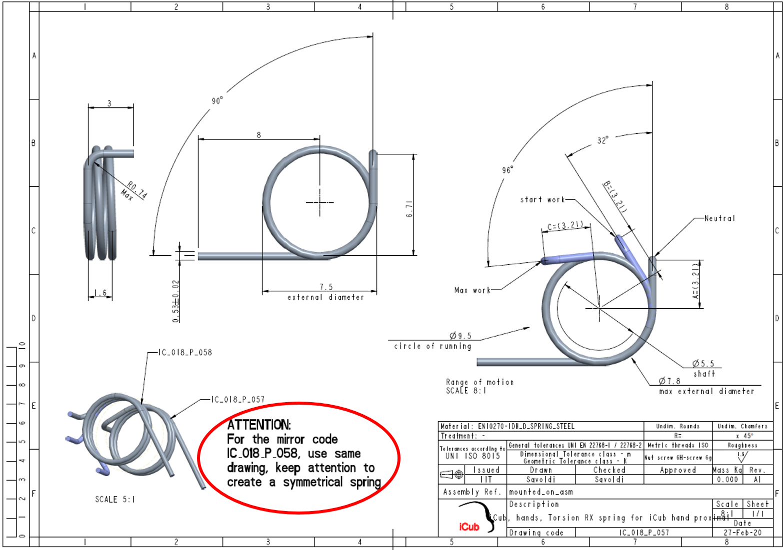
In cases where the mirrored parts are sent for production along with the original parts, a separate drawing file for the mirrored part is not strictly necessary. However, it is important to specify that the production of the mirror-symmetric part should be followed by referring to the drawing of the original part by:
- creating a text note in the drawing file of the original part (see figure below for example)
- adding a note in the product documentation (
BOMforMWS.xlsxor other related documents)
The designer shall prepare separate drawings for mirrored parts only for cases when deemed useful by the designer.
Robot assembly coding shall be performed according to the robot assembly variants description.
- The iCub variants are described in the iCub variants page
- The R1 variants are documented in the R1 variants page
When working with external collaborators, especially with surface-based 3D models like covers, we prefer to receive the following files from external designers:
- Surface-based 3D models define the maximum volume (i.e. the internal skin) of the robot covers.
-
OPTIONAL: Solid 3D models that define the desired results (only for reference).
The IIT internal designers shall then design solid covers based on the provided surfaces. The surfaces can be imported in the parts using an import feature. The import feature in this case must be unique and must be the first feature of the model tree.