HydraFW UART guide - hydrabus/hydrafw GitHub Wiki
HydraFW Bus UART (Universal Asynchronous Receiver/Transmitter)
This guide is updated towards firmware release HydraFW v0.11 and later
Bus: UART, MIDI (universal asynchronous receiver transmitter).
Connections: two pins (RX/TX) and ground.
Output types: 3.3volt normal output, or open drain
(pull-up/pull-down resistors integrated in MCU or external).
Pull-up resistors: required for open collector output mode (2K – 10K).
Pull-up/down resistors Integrated in MCU: Between 30 to 50K (Typical 40K).
Maximum Voltage: 5.5volts (5volt safe).

UART is also known as the common PC serial port.
The PC serial port operates at full RS232 voltage levels
(-13volts to +13volts) though, which are not compatible with the HydraBus.
Protocol configuration syntax description:
-
showShow UART parameters orshow pinsShow pins used in this mode -
devicewith parameter1or2to choose UART device (1 or 2) -
speedwith integer baudrate value (supportk,msuffix or no suffix)- UART1 Baudrate from
1281and up to10.5M - UART2 Baudrate from
640and up to5.25M - Standard UART baudrate: 2400, 4800, 9600, 19200, 38400, 57600, 115200, 31250
- UART1 Baudrate from
-
paritywith parameternoneorevenoroddfor parity value -
stop-bitswith parameter1or2for number of stop bits -
bridgeto enter USB <-> UART mode -
triggerconfigures the trigger mode -
scantries to calculate the baudrate (See baudrate detection) -
timeoutsets a global timeout on read operations. Once timed out, an operation will only return bytes read along with an error message. -
exitto exit UART mode
Note default value for device 1 or 2:
For device 1 (UART1):
> uart device 1
Note: UART parameters have been reset to default values.
Device: UART1
Speed: 9600 bps
Parity: none
Stop bits: 1

For device 2 (UART2):
> uart device 2
Note: UART parameters have been reset to default values.
Device: UART2
Speed: 9600 bps
Parity: none
Stop bits: 1
Configuration options:
Hardware Informations:
uart1> show pins
TX: PA9
RX: PA10

uart2> show pins
TX: PA2
RX: PA3
Protocol configuration example:
Configuration of UART1 9600bauds 8bits data, 1stop, no parity:
> uart device 1
Note: UART parameters have been reset to default values.
Device: UART1
Speed: 9600 bps
Parity: none
Stop bits: 1
Protocol interaction syntax description:
Protocol interaction example usage UART1 write:
uart1> 0xFF 0 1 0x80 0x55 0xAA 0xFF 0x11:4
WRITE: 0xFF 0x00 0x01 0x80 0x55 0xAA 0xFF 0x11 0x11 0x11 0x11
Bridge mode
Hydrabus can be used as a USB to UART bridge with the bridge command :
> uart
Device: UART1
Speed: 9600 bps
Parity: none
Stop bits: 1
uart1> bridge
Interrupt by pressing user button.
Baud rate detection
Since cb2ebea9f694a344fee28b2baf4e160f7066dcf2, Hydrabus can automatically detect the baudrate on a UART line.
In order to do that, connect the device TX line to PC6, and run the scan command :
uart1> scan
Estimated baudrate : 57712
The baudrate detection waits for at least 10 bytes sent to the UART, then measures the shortest transition to calculate the baudrate. This means that you need to make sure that bytes are sent on the target UART in order to measure the signal.
UART baudrate and error
Example of baudrates and related error:
Extreme baudrate example:
| Baudrate | 10,500,000 | 8,400,000 | 6,000,000 | 5,250,000 | 4,000,000 |
|---|---|---|---|---|---|
| Final baudrate | 10,500,000 | 8,400,000 | 6,000,000 | 5,250,000 | 4,000,000 |
| Error % | 0.000 | 0.000 | 0.000 | 0.000 | 0.000 |
| Baudrate | 3,000,000 | 2,000,000 | 2,500,000 | 1,000,000 | 921,600 |
|---|---|---|---|---|---|
| Final baudrate | 3,000,000 | 2,000,000 | 2,470,588 | 1,000,000 | 923,076 |
| Error % | 0.000 | 0.000 | 1.190 | 0.000 | 0.160 |
Standard baudrate example:
| Baudrate | 460,800 | 250,000 | 230,400 | 115,200 | 57,600 | 38,400 |
|---|---|---|---|---|---|---|
| Final baudrate | 461538 | 250,000 | 230,136 | 115,226 | 57,613 | 38,408 |
| Error % | 0.160 | 0.000 | 0.110 | 0.030 | 0.030 | 0.030 |
baudrate from 33,600 to 2400 bauds 0% error
Additional information about baudrate error:
- https://www.robotroom.com/Asynchronous-Serial-Communication-2.html
- Important information:
Therefore, to be fair, each device is only allowed to be less than 2.5% in error, to ensure that the total difference in timing between devices is less than 5%. To provide a safer margin, Atmel recommends a 2% error or less per device.
Additional informations about UART
For more details on UARTprotocol see: http://en.wikipedia.org/wiki/Universal_asynchronous_receiver/transmitter
Tests & informations from Philippe Teuwen Wiki: https://wiki.yobi.be/index.php/HydraNFC#HydraBus_UART
Recommended USB High Speed to UART interface (for real-time data input/output using High Speed UART)
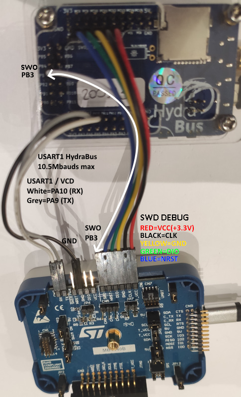
STLINK-V3SET USB2.0 HS interface (USB CDC up to 10.5MBaud)
Support HydraBus v1 UART1(PA10/USART1_RX & PA9/USART1_TX) up to 10.5Mbaud
FTDI USB2.0HS interface (USB CDC support up to 8.4MBaud)
-
FTDI interface C232HM-DDHSL-0 (3.3V Output Level, 0.5M cable) See https://wiki.yobi.be/index.php/HydraNFC#HydraBus_UART
-
I recommend to use FTDI C32HM-DDHSL-0 cable with 6MegaBaud (8N1) settings on both side (tested with HydraBus uart1 bridge & FTDI C232HM-DDHSL-0)
-
Datasheet: https://www.ftdichip.com/Support/Documents/DataSheets/Cables/DS_C232HD_UART_CABLE.pdf
-
UART FTDI C232HM-DDHSL-0 to HydraBus connection:
C232HM-DDHSL-0 Pin HydraBus Pin Orange ADBUS0 TX(Pin2) PA10 / USART1_RX Yellow ADBUS1 RX(Pin3) PA9 / USART1_TX Black GND (Pin10) GND (near PA9)
- Note1: FTDI C232HM-DDHSL-0 Baudrate of 8.4MBaud is possible when setting the FTDI C232HM-DDHSL-0 to any value greater or equal to 6.3MBauds.
- Note2: FTDI C232HM-DDHSL-0 Baudrate of 8.4MBaud DutyCycle is 46.4% / 53.6% or the reverse so up to +/-3.6% error/variation but still works with HydraBus configured @8.4MBauds.
- Warning: FTDI C232HM-DDHSL-0 Baudrate values like 6.2MBauds, 6.6MBauds, 7.1MBauds, 7.7MBauds set the FTDI Baudrate to 115.2KBauds.
-
-
FTDI C232HM-EDHSL-0 (5V Output Level, 0.5M cable) => Not tested