Model View Projection Matrices in OpenGL - hls333555/OpenGL GitHub Wiki
Download maths library from glm and extract glm folder into our vender folder.
For detailed explanation of matrices, check this tutorial: Matrices in OpenGL.
For more information on transformations in OpenGL, check this website: OpenGL Transformation.
For more information regarding coordinate systems in OpenGL, check this tutorial: Coordinate Systems.
The Model Matrix
In 3D graphics we will mostly use 4x4 matrices. They will allow us to transform our (x,y,z,w) vertices. This is done by multiplying the vertex with the matrix :
Matrix x Vertex (in this order !!) = TransformedVertex
// The identity matrix
glm::mat4 myIdentityMatrix = glm::mat4(1.f);

// Translation matrix - Translate a vector of 10 units in the X direction
glm::mat4 myTranslationMatrix = glm::translate(glm::mat4(), glm::vec3(10.f, 0.f, 0.f));

// Rotation matrix
glm::vec3 myRotationAxis(x, y, z);
glm::mat4 myRotationMatrix = glm::rotate(angle_in_degrees, myRotationAxis);

// Scaling matrix - Scale a vector by 2.0 in all directions
glm::mat4 myScalingMatrix = glm::scale(2.f, 2.f, 2.f);

// The model matrix
// !!! BEWARE !!! These lines actually perform the scaling FIRST, and THEN the rotation, and THEN the translation. This is how matrix multiplication works.
glm::mat4 myModelMatrix = myTranslationMatrix * myRotationMatrix * myScalingMatrix;
glm::vec4 myTransformedVector = myModelMatrix * myOriginalVector;
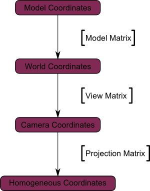
After applying the model matrix to all vertices at each frame (in GLSL, not in C++!), everything moves, and something that doesn’t move will be at the center of the world, which means that all vertices are converted from Model Space (all vertices defined relatively to the center of the model) to World Space (all vertices defined relatively to the center of the world).
The View Matrix
There is no separate camera (view) matrix in OpenGL. Therefore, in order to simulate transforming the camera or view, the scene (3D objects and lights) must be transformed with the inverse of the view transformation. In other words, OpenGL defines that the camera is always located at (0, 0, 0) and facing to -Z axis in the eye space coordinates, and cannot be transformed.
Initially the camera is at the origin of the World Space. In order to move the world, you simply introduce another matrix. Let’s say you want to move the camera of 3 units to the right (+X), which is equivalent to moving the whole world (meshes included) 3 units to the LEFT (-X):
glm::mat4 myViewMatrix = glm::translate(glm::mat4(), glm::vec3(-3.f, 0.f, 0.f));
Now, all vertices are converted from World Space (all vertices defined relatively to the center of the world) to Camera Space (all vertices defined relatively to the camera).
The Projection Matrix
A computer monitor is a 2D surface. A 3D scene rendered by OpenGL must be projected onto the computer screen as a 2D image. The actual transformation that happens with the projection matrix is that all the positions are converted into a normalized space called NDC (Normalized Device Coordinates) and then be mapped to the window. The normalized space is a coordinate system between -1 and 1 in every axis, that's to say, no matter what resolution the window is, the left side is always -1 while the right side is always 1, the bottom side is always -1 while the top side is always 1. Any vertices that are outside this range are not rendered and get culled for they are outside of the frustum.
There are two main projections illustrated below:

For now we just demonstrate the orthographic projection.
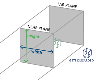
An orthographic projection matrix defines a cube-like frustum box that defines the clipping space where each vertex outside this box is clipped. When creating an orthographic projection matrix we specify the width, height and length of the visible frustum. All the coordinates that end up inside this frustum after transforming them to clip space with the orthographic projection matrix won't be clipped. The frustum looks a bit like a container:

To create an orthographic projection matrix we make use of GLM's built-in function glm::ortho():
glm::mat4 myProjectionMatrix = glm::ortho(-2.f, 2.f, -1.5f, 1.5f, -1.f, 1.f);
The first two parameters specify the left and right coordinate of the frustum and the third and fourth parameter specify the bottom and top part of the frustum. With those 4 points we've defined the size of the near and far planes and the 5th and 6th parameter then define the distances between the near and far plane. This specific projection matrix transforms all coordinates between these
x,yandzrange values to NDC.
In fact, you can change the orthographic projection matrix to one-to-one pixel mapping based on the window resolution:
window = glfwCreateWindow(960, 540, "Hello World", NULL, NULL);

glm::mat4 myProjectionMatrix = glm::ortho(0.f, 960.f, 0.f, 540.f, -1.f, 1.f);
Then modify the position data accordingly:
float positions[] = {
    100.f, 100.f, 0.f, 0.f, // 0
    200.f, 100.f, 1.f, 0.f, // 1
    200.f, 200.f, 1.f, 1.f, // 2
    100.f, 200.f, 0.f, 1.f  // 3
};
We can actually test NDC by adding the following code:
glm::mat4 proj = glm::ortho(0.f, 960.f, 0.f, 540.f, -1.f, 1.f);
glm::vec4 vp(100.f, 100.f, 0.f, 1.f);
glm::vec4 result = proj * vp;
If you add a breakpoint and watch the value of result, you will notice that the projection indeed convert the (100.0, 100.0) to be in that [-1, 1] space:

Putting it all together

// C++: compute the MVP matrix
glm::mat4 MVPmatrix = myProjectionMatrix * myViewMatrix * myModelMatrix; // Remember: inverted!

int location = glGetUniformLocation(program, "u_MVP");
// Send MVP matrices to the shader
glUniformMatrix4fv(location, 1, GL_FALSE, &MVPmatrix[0][0]);
// GLSL: apply it
uniform mat4 u_MVP;
void main()
{
	gl_Position = u_MVP * position;
	//...
}
