Connection Board - hampussandberg/HexConnect GitHub Wiki

Top View
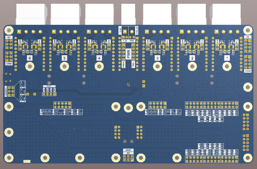
Bottom View
Schematics can be found here.
One of the main task for the connection board is provide power to the other boards that are connected to it. There are two main input power sources:
- 5V_USB/BATTERY
- 5V_MODULE
The user can choose to use either one of these. Onboard is also a LTC4415 which is a dual ideal diode, basically a circuit that makes it possible to have two input power sources connected to the same power rail. This chip takes care of switching between the two sources if both are connected at the same time, 5V_MODULE has highest priority. Information on which power source is active is sent to the UI Processor Board.
As the LTC4415 is a bit expensive it's also possible to skip this chip (don't populate it) and instead put a 0R resistor on R12 and R13. IMPORTANT NOTE: If the LTC4415 is not used and both R12 and R13 are mounted the user has to make sure NOT to connect both supplies at the same time, only one should be connected.
Power to each of the six modules is controlled by TPS22960 load switches. All switches are controlled by the Data Processor Board trough a PCF8574 I/O expander.
A socket for a CR1220 battery is located under the UI Processor Board to provide power to the RTC when the external power is removed. This also has a small diode in series to protect against reverse polarity.
The battery connecter is for a future attachment.
The battery connector has the following pinout:
| Header | Name |
|---|---|
| 1 | 5V_USB/BATTERY |
| 2 | GND |
| 3 | 5V_USB/BATTERY |
| 4 | GND |
| 5 | I2C_UI_SDA |
| 6 | I2C_UI_SCL |
The I2C bus is meant to be used to have communication possible between the UI Processor and a potential MCU on the battery board that measures current, battery capacity, etc.
Connection to the different modules is done trough a 4-pin, 5.08mm pitch, pluggable terminal block. These are available from many different manufacturers, for example TE Connectivity 282814-4 with mating connector 796634-4. These have a rating of around 15A / 300VAC which should be enough for any present and future module. A similar but 2-pin connector is used for the power module, for example TE Connectivity 282814-2 with mating connector 796634-2.
The headers used to connect the modules to the connection board are 10-pin, 2.54mm pitch, female headers. These can be found almost everywhere for a small cost. The distance between the two headers is 20.32mm or 800mil, this way the modules are "breadboard friendly" and a module can be designed using a 100mil pitch prototype board that are commonly available.
Connected to pin 3,4 and 17,18 of each module is two headers called MnR and MnL (where n is the number for the module). At the current moment these pins are not used by any module but can be used in the future if for example the module require a high current/voltage to drive a motor. One possible usage for the connection board could be as a 3D printer controller board with 4 motor driver modules.
In parallel with MnR and MnL are also two U.FL connectors. As standard these are not populated and are disconnected from MnR and MnL. If a user wants to use these connectors some 0R 0603 resistors has to be soldered to the board. The GND connection of the U.FL connector can either be connected to one pin of MnR/MnL or to the GND plane on the connection board.
The I2C bus connected to the UI Processor is available on a 4-pin 2.54mm pitch header with the following pinout:
| Header | Name |
|---|---|
| 1 | PWR* |
| 2 | GND |
| 3 | SDA |
| 4 | SCL |
* PWR can be set to 3.3V_UI or 5V using two jumpers
This can be used to connect extra peripherals that need to communicate with the UI Processor in the future.
On the left side of the board, under the Data Processor there is an AD5593R. This is an 8-channel, 12 bit ADC/DAC and it's connected to the Data Processor Board.
There is also a MCP9808T temperature sensor connected to the UI Processor Board.
The board is 4 layer, 180x100 mm. It has multiple mounting holes that can be used to secure it to a case.
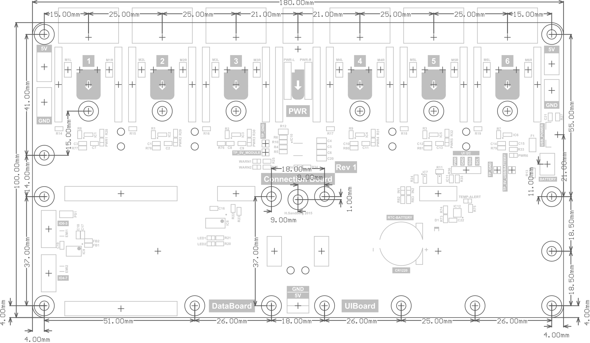
Mechanical Drawing