Upconverter - ha7ilm/opendous GitHub Wiki
Converts signals in the MF and HF Bands (0.5MHz to 50MHz) to signals in the VHF Band (125.5MHz to 175MHz) for the 125MHz version. Intended for use in receiver applications with projects like RTL-SDR/SDR# or FunCube Dongle.
The board was designed using the Free and Open-Source Software KiCad and QUCS. All design files are Open Hardware and released into the Public Domain under Creative Commons CC0.
There are two versions of this Upconverter that differ in the LO and IF/Output filters, a 100MHz version and a 125MHz version version.
Available from NooElec Online or eBay.
KS4JU at HamRadioScience has a review of the board and has posted a tutorial video.
Questions or comments? Visit the Opendous Google Group. There is also a FAQ, detailed explanation of the design, and additional testing results. W2AEW has a video explaining Upconverter design.
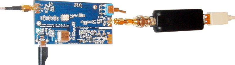
Upconverter in action with DVB Dongle
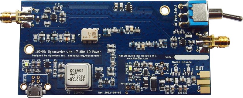
125MHz Upconverter
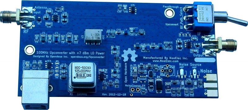
Only the IF Output filter and LO Filter were updated compared to the previous version.
The design files can be found in SVN or downloaded as an archive.
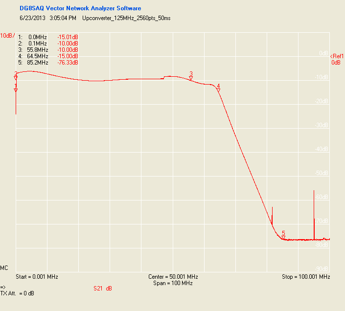
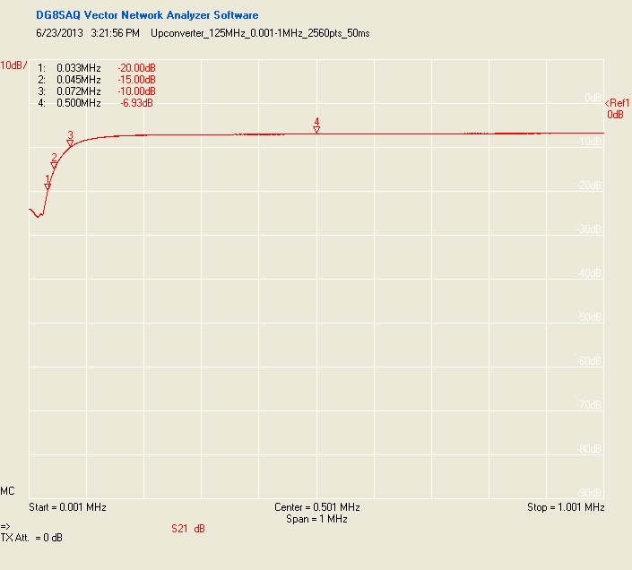
125MHz Upconverter Upconversion Losses
The 125MHz Upconverter has Upconversion Losses (data) of approximately 10dB from 0.1MHz to 55.8MHz and 15dB from 45kHz to 64.5MHz (data). The 1dB compression point is at +1dBm (this is the maximum input signal level before distortion occurs).
100MHz Upconverter
The design files can be found in SVN or downloaded as an archive.
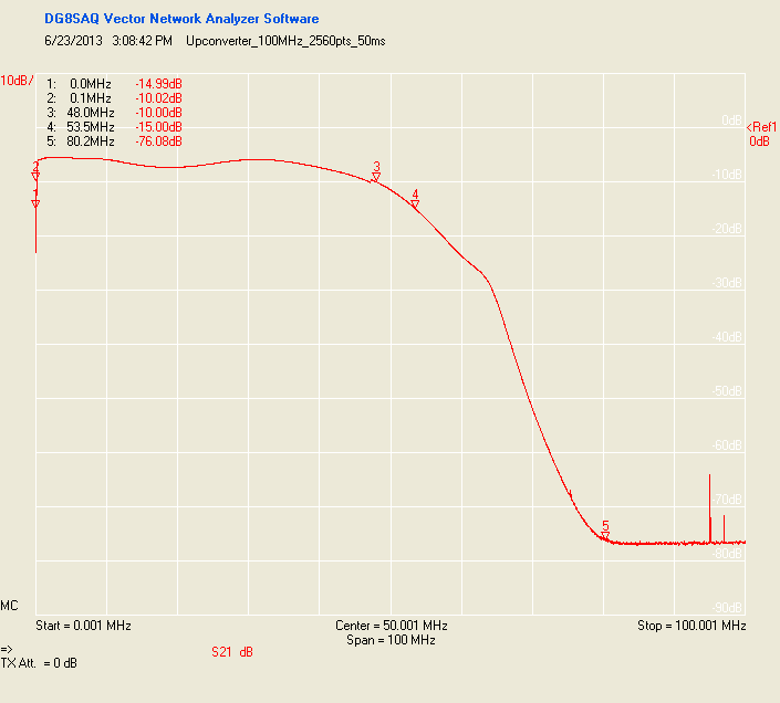
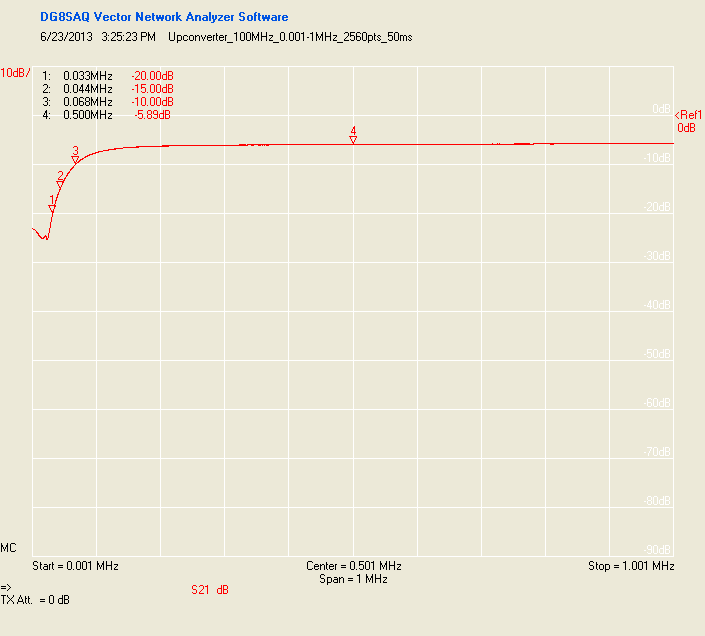
100MHz Upconverter Upconversion Losses
The 100MHz Upconverter has Upconversion Losses (data) of approximately 10dB from 0.1MHz to 48MHz and 15dB from 45kHz to 53.5MHz (data). The 1dB compression point is at +1dBm (this is the maximum input signal level before distortion occurs).
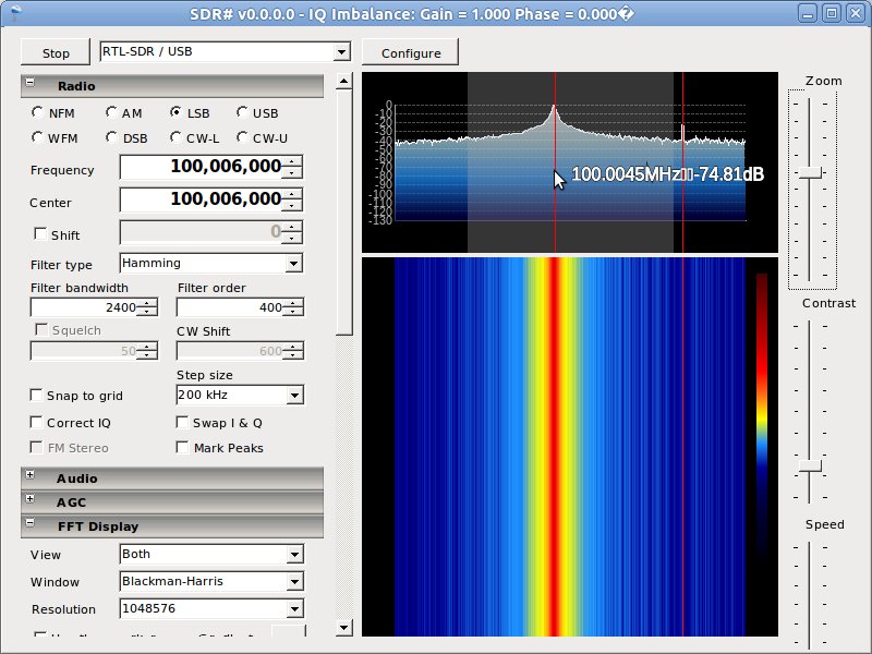
SDR Software Tuning Instructions
With your Upconverter input shorted or unconnected, tune your SDR software to several kHz above the Upconversion frequency (100.06MHz or 125.06MHz depending on version). Note where the nearest peak is (other than 100.06MHz/125.06MHz where you will see the DC spike) in the FFT display. This value takes into account any frequency offset from the Receiver/Demodulator. Since the 25ppm 100MHz oscillator is likely more precise than the Receiver/Demodulator, subtract the Upconversion frequency from the value to get the Receiver/Demodulator offset (in the picture below it would be 100.0045-100=0.0045). To tune to a Shortwave band such as 9.5MHz, simply add 9.5 to 100 and subtract the offset (9.5 + 100 - 0.0045 = 109.4955). With a high enough SDR sampling speed (0.5MSPS+) you will now be able to make out communication signals you can further tune to.
Optional Noise Source
See Upconverter_NoiseSource for more information.
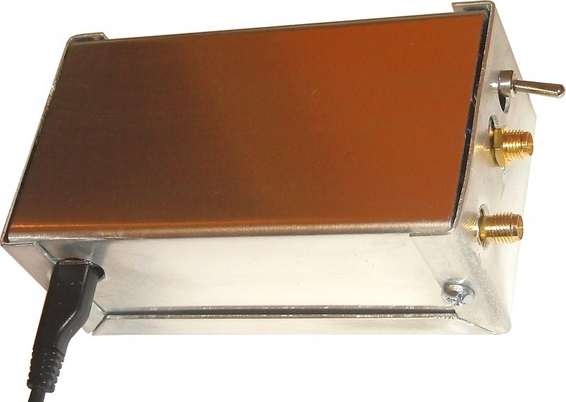
Enclosure
See the Upconverter Enclosure Fabrication Instructions.
FAQ
It doesn't work! : Please first check all connections and try different cables. Then try a different USB power source (different port on PC, no hub). Then put the Upconverter into Upconvert mode and connect to your receiver tuned to 125.01MHz to see the LO bleed. You should be able to receive the 125MHz LO signal from the mixer which is about -45dBm at the IF/OUTput port.
I cannot receive any signals : If the above doesn't help, try a better/larger antenna. A quick hack is to connect the Upconverter INput to a large piece of safe exposed household metal such as a metal sink and its pipes or radiator. I recommend avoiding use of RF equipment during lightning storms or when lightning is forecast. You should be able to receive AM radio stations (0.5-2MHz) by tuning your receiver to 125.5-127MHz when connected to the Upconverter in Upconvert mode.
Can I connect two receivers to the same Upconverter? : Yes, but the two receivers must have inputs that are compatible with each other. The safest option is to make sure both receivers have no DC feed through a bias tee or disable this option. The receivers could damage each other if one or both have a DC bias. The output of the Upconverter is DC-Blocked so you do not need to worry about it unless dealing with high power levels (> +10dBm). SMA Splitter Adaptors can be found on eBay. Note the Upconverter uses SMA Jack (Female) connectors, not RP-SMA.
Why not add an amplifier to overcome the 10dB conversion loss? : Since the Noise Figure of an RF system is most dependent on the Noise Figure of the first elements in the signal chain, it does make sense to place an LNA at the antenna port. I just wasn't sure if most users would have their Upconverter at their antenna.
Can it be used for Transmitting? : Sure, there are no one-way paths in the Upconverter. If you have a VHF transmitter that operates in the 100MHz to 150MHz range then the Upconverter can be used in reverse as a down-converting mixer to broadcast over 0.5MHz to 50MHz (downconverted 100.5MHz to 150MHz signal). All you would need is a Power Amplifier and bandpass filter for your intended frequency range at the RF port and an attenuator at the IF port if the transmitting signal was above 0dBm.