AD_Micropendous1BaseDevelopmentBoard - ha7ilm/opendous GitHub Wiki
All KiCAD design files for this board are available through SVN. This design is "abandoned" as two of the connectors are too close. A small lot of these boards was produced before the error was noticed so this page is useful to those who have one.
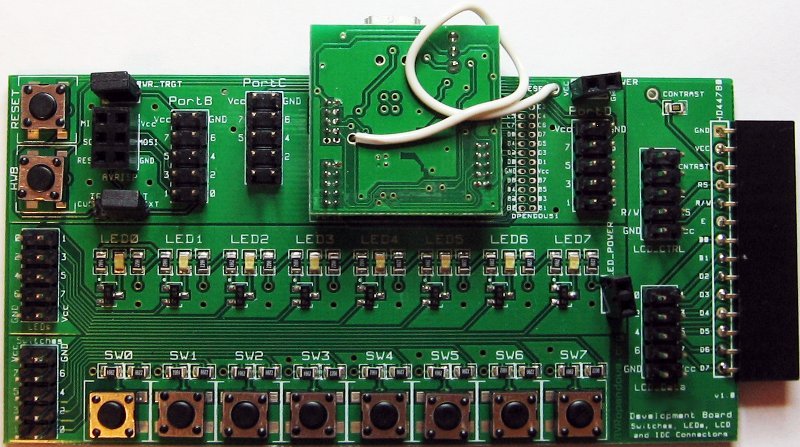
The Micropendous1-Base Development Board is an adapter board to convert the pinout of the Micropendous1-Base to IDC-compatible headers with the same pinouts as an Atmel STK500 development board. It also features LEDs, buttons, and an adapter for a HD44780 LCD display in order to simplify the use of USBVirtualSerial-LCD firmware.
Assembly
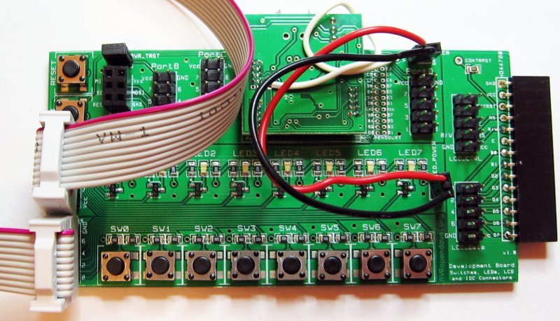
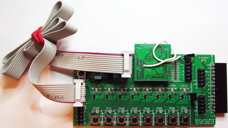
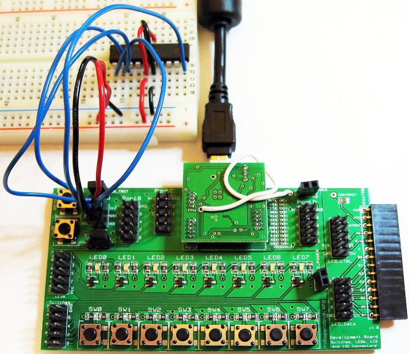
Plug your Micropendous1-Base in an inverted fashion into the adapter board:
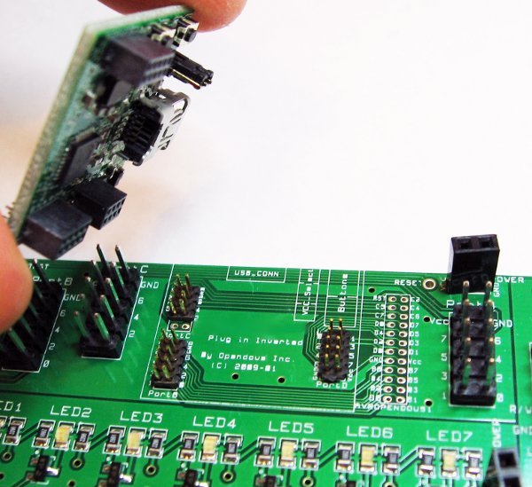
To make full use of the adapter board, you must connect the RESET (PC0) of the Micropendous1-Base to the RESET of the adapter board. In the picture below it is the white wire. Solder or use conductive epoxy to connect the two.
Testing
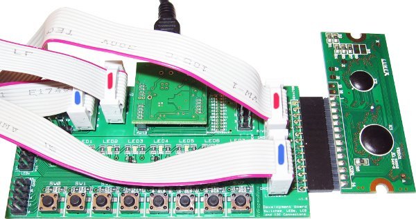
To test the adapter board, load your Micropendous1-Base with MicropendousKeyboardTest firmware, plug the complete adapter board into a PC, then connect each port in turn to the switch array (making sure to to keep the red wire on the VCC-GND side of the connectors). Pressing each switch should type a different letter. Note PortC only has 5 connections.
Buttons and LEDs
The following is the schematic of the Buttons and LEDs. It is the same as the STK500.
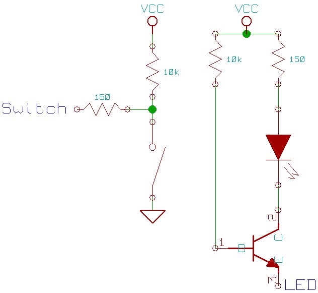
Unfortunately, the LEDs and Buttons headers are too close to use IDC headers to connect the two, hence the status of this design as "abandoned".
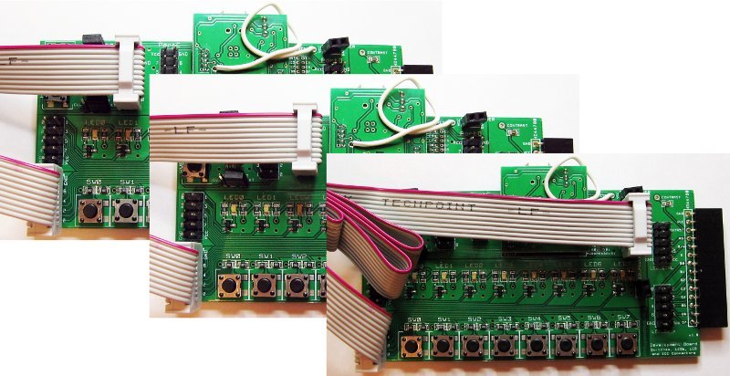
You can connect a port to the LEDs thusly:
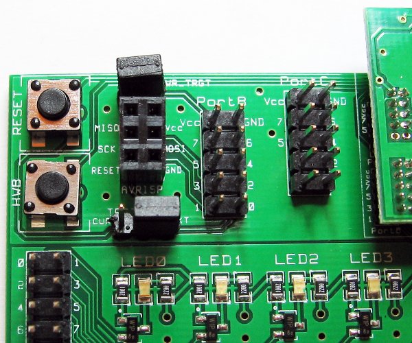
AVR ISP Programming
By properly setting up the jumpers:
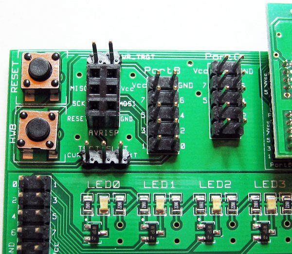
you can use the board (programmed with AVR ISP Programmer firmware) to simplify programming of external AVRs through ISP.
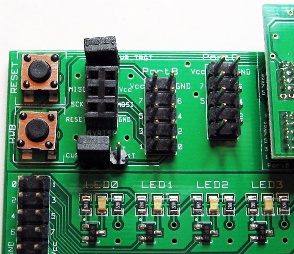
Programming External AVR MCUs
After programming your Micropendous1-Base on the adapter board with AVR ISP Programmer firmware, set the TRGT jumper to EXT and mount the PWR_TRGT jumper. You can now connect the SPI port to an external AVR and program it while also providing power to the target AVR at the same voltage as the VCC_Select jumper on the Micropendous1-Base.
Programming Self-Powered External AVR MCUs
This procedure is the same as the one above, just dismount the PWR_TRGT jumper.
After programming your Micropendous1-Base on the adapter board with AVR ISP Programmer firmware, set the TRGT jumper to EXT and dismount the PWR_TRGT jumper. You can now connect the SPI port to an external AVR and program it. This setup assumes the target AVR is self-powered. Set the VCC_Select jumper on the Micropendous1-Base to the closest voltage of the target MCU. You may need a voltage translator if the voltage difference is more than 0.5V.
Programming your Micropendous1-Base through ISP
If you set the TRGT jumper to CURR and mount the PWR_TRGT jumper, then you can connect an external AVR ISP Programmer through the SPI port, even another Micropendous1-Base, and program the Micropendous1-Base connected to the adapter board. This is useful if you wish to change the bootloader on your Micropendous1-Base. The Micropendous1-Base being programmed should NOT be connected through USB to a PC while it is being programmed.
LCD
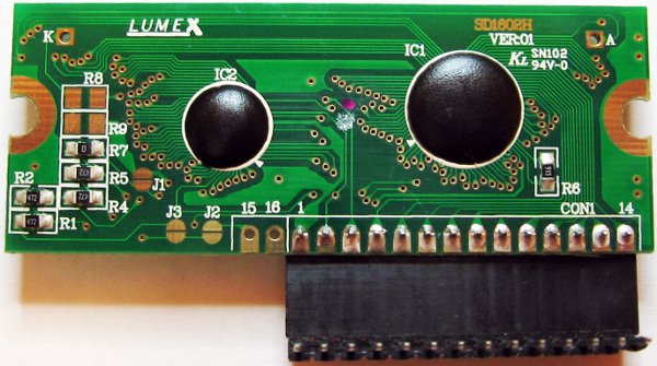
The Lumex LCM-S01602DTR/M, pictured, is the LCD that the board was supposed to be designed for but must be plugged in backward. The Lumex LCM-S01602DSF/A is an LCD with a proper pinout for this adapter board. The two pinouts are the inverse of each other.
As you can see in the next photo, simply connect PortC to LCD_CTRL and PortB to LCD_DATA and program USBVirtualSerial-LCD 2Port version firmware onto your Micropendous1-Base board to use this functionality.