Lab 3 - gracie-miller/BAE305-S19 GitHub Wiki
Lab 3 - Circuit Simulation
By: Gracie Miller and Rachel Rohrer
Summary
The goal of this lab was to get acquainted with using a circuit simulator to analyze circuits. After building physical circuits using a breadboard, the voltages across resistors within the circuit were measured. Then, the same circuits were built within a circuit simulator. The simulated voltage drops and currents through resistors were recorded. For the most part, we found that the circuit simulator was consistent with the physical measurements.
Materials
- JAMECO Breadboard JE27
- resistors
- 200 ohm
- 470 ohm
- 1K ohm
- 2.2K ohm
- 3.3K ohm
- 4.7K ohm
- 5.1K ohm
- 6.8K ohm
- 10K ohm
- connecting wires
- Global Specialties 1301A Power Supply
- Partsim Online Circuit Simulator
Assembly Procedures
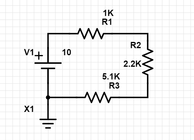
- Build the first circuit according to the given schematic. Set the voltage provider to 10V.

- Build the same circuit in the circuit simulator.
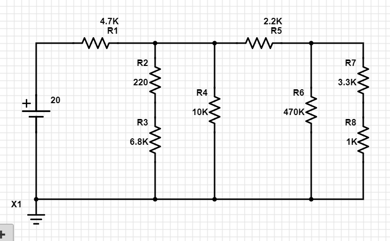
- Build the second circuit according to the provided schematic. Set the voltage provider to 20V.

- Build the same circuit in the circuit simulator.
Test Equipment
- Fluke 87 True RMS Multimeter
- LT Spice Analysis program (through Partsim)
Test Procedures
- For each circuit, measure the voltage drop across each resistor by placing the leads of the DMM on each side of the resistor and record the values.
- For the circuit simulator, click run on the LT Spice analysis. Check the box for Transient Analysis and set the time for a small increment. When using the simulator to measure current through resistors, be sure the use the probe function and add the probes for the necessary resistors. Record the values.
Test Results
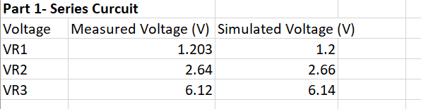
Part 1:
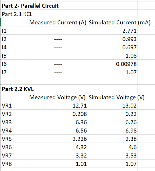
Part 2:
Part 3:
This circuit was used to calculate the results

Using the voltage division formula shown, an excel formula was derived to find the sensor resistance (R2) using the max unknown resistance (R1 on the circuit diagram, R? on the spreadsheet)
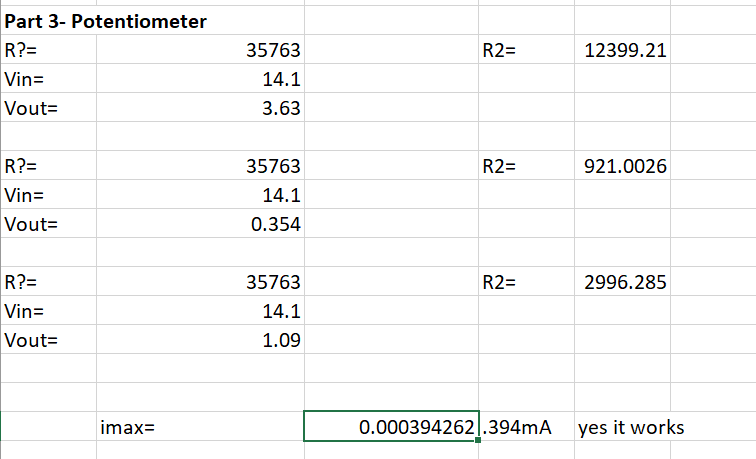 The excel formula referenced appropriate cells to accomplish R2 = ((Vout/Vin)*R?) / (1-(Vout/Vin))
Discussion
- Q1: As it can be seen in the above table, the currents I5, I6, and I7 entering and leaving the node equals zero. (-1.08+0.00978+1.07)mA ~ 0mA
- Q2: The voltage across the branch containing R2 and R3 was very close to the voltage across the branch containing R4. This is because the voltage across the same components in parallel is the same, and the combined resistance of R2 and R3 is relatively close to 10K ohms.
- Q3: There is a difference in the voltage across some branches because the not all the branches contain components of similar resistances to one another.
- Q4: As can be seen in the results for Part 3, when Vout = 3.63V R2 = 12.4K ohms.
- Q5: When Vout = 0.354V, R2 = 921 ohms.
- Q6: When Vout = 1.09V, R2 = 3.0K ohms.
- Q7: If the maximum current for the sensor is 0.4mA, the sensor will still work because the maximum current for the circuit is 0.394mA