Hydra - gorawen/open_evse GitHub Wiki
For the page on the standalone variant of the Hydra, go here.
The Hydra
We have 6 L2 J1772 chargers and a CHAdeMO at work. For various reasons, my colleagues are more politically attuned to EV ownership than the general population, even here in the SF Bay area. So those chargers are oversubscribed. What makes it worse is that most of those cars are Leafs, which only charge from those L2 chargers at 15A. Since the chargers are 30A, half the potential is being wasted. Why they don't just use the CHAdeMO is beyond me.
It would be easy to make a box with a square wave generator to dummy up a pilot to feed two cars from a J1772 inlet, but that would neither be spec compliant, nor safe. No, the correct thing to do is to intelligently allocate the incoming power to the two cars as needed.
And thus, the Hydra was born.
Details
The Hydra owes much of its existence to OpenEVSE. Some of its circuitry was cribbed from the OpenEVSE Plus. The Hydra has the same 16 MHz ATMega controller as the OpenEVSE and Arduino Uno. Connected to that are the following subsystems:
- A comparator to convert the incoming pilot signal into a TTL compatible square wave so that the controller can determine the duty cycle, and thus, the ampacity of the host EVSE.
- A comparator to watch for transitions on the incoming proximity pin. The controller will gracefully shut down both cars if the proximity resistance rises above 300 ohms (or so).
- Two pilot signal generators. Analog switches are used to create a +/- 12 volt square wave from +/- 12 volt regulated power supplies. The PWM timer systems of the controller are used to generate the varying duty cycles.
- Resistor networks feed the outgoing pilots back into the controller on two analog pins so that state changes and diode failures on each car can be detected.
- Each car has a current transformer on one of its hot leads so that the car's current draw can be monitored. If a car exceeds its allocated current, it is shut down.
- The Hydra has an RGB LCD display to show status information.
The shared mode in the Hydra has the following rules:
- If no car is charging, both cars get 100% of the incoming pilot.
- If one car is charging, it gets 100% and the other car gets 50%.
- If both cars are charging, both cars get 50%.
- If both cars are charging and one stops, the other pilot is immediately raised to 100%. The car that stopped continues to get 50% in accordance with the above rules.
- If only one car is charging, and the other enters state C, it will be given a delay. During that delay, the other car's pilot is reduced to 50% and it will be given a brief interval to respond and reduce its draw. After the delay, the second car's power will be turned on.
- If any car exceeds its current allowance for for too long, it is errored out.
- If any car fails a diode check at any time, it is errored out.
- If any car enters an invalid state (7.5 volts, for instance - between B and C), it is errored out.
- If the incoming pilot drops below the 12A minimum (because that's the smallest that can legally be split in half) or stops being a valid pilot, both cars are errored out.
- If the proximity is pushed on the inlet, both cars are errored out.
- If a car is errored out, its plug must return to state A to clear the error (so pull the plug out and reinsert it).
The sequential mode operates by giving a full-power pilot to only one car at a time. The first car to be connected after establishing sequential mode will be given the pilot. It will keep the pilot until it transitions from mode C or D back to B. When it does so, if another car is connected (and in state B), then it will be given the pilot, and the pilot will be taken away from the first car. Both cars will "pass the baton" back and forth. A car entering state C without its pilot being enabled will result in a "T" (illegal transition) error.
The Hydra does not attempt to detect L1 vs L2 - it only cares about amps. It also doesn't attempt to detect ground faults - the source EVSE is assumed to have its own GFCI. Also, my prototype does not include fuses or breakers - again, the source EVSE is assumed to have over-current protection.
The board has the following interface points:
- 2 two pin terminals for the coils for two power relays for car A & B
- 2 two pin terminals for the current transformers for car A & B
- 2 three pin terminals - one for each car that has the outgoing pilot and proximity signals, plus a ground connection
- 1 three pin terminal that comes from the inlet, with ground, pilot and proximity
- 1 two pin terminal that brings 12 VDC from an external power supply
- 1 two pin terminal that connects to an external power switch. This switch switches the inlet pilot resistance from state B to state C when closed. Optionally, you can simply jumper the terminal if you would rather. The v2.x hardware includes a transistor that will hold the inlet in state C whenever at least one car is powered up.
- 1 2x3 pin ISP socket for programming
- 1 6 pin FTDI header for serial I/O (for debugging, programming or future expansion)
There are some things on the board that require some attention:
- R14 (on Google Code) and R17 (on Google Code) are burden resistors for the CT coils. These need to be chosen based on the CT you're going to use and the maximum outlet current rating for your Hydra. For my prototype, the CTs I've selected have a Te of 1018 and the design current for the Hydra will be 30A. For that configuration, a 56 ohm resistor is appropriate. You'll also find a #define in the source code for the Hydra that you will need to adjust in concert with this. Customizing the burden resistor allows you to maximize the accuracy of the ammeter readings for each car.
- The PROX_RES jumper enables a 2.7k resistor between the inlet proximity pin and ground. If your inlet lacks a 2.7k resistor between proximity and ground, then close this jumper.
- The DTR_RESET jumper will allow the serial port DTR signal to reset the controller. If you're going to use an FTDI cable with an Arduino bootloader to upload sketches, then you should close this jumper. If you're going to use, for example, bluetooth modules on this port, then you probably want to leave it open.
- The BL_COM_SEL 2 way jumper selects the polarity of the backlight common pin. If your LCD module is common anode, then pads 2 and 3 should be closed. If your LCD module is common cathode, then pads 1 and 2 should be closed. DO NOT close all three pads - that would short out the 5 volt power supply. Note that if you use a common cathode backlight, you will need to compile the firmware with that option set.
The software is hosted on GitHub at https://github.com/nsayer/hydra
You have two choices on programming the Hydra. First, you can program using an AVR ISP programmer connected to the 6 pin ISP socket. This is exactly the same way OpenEVSE is programmed.
Alternatively, if you do not have an AVR ISP programmer, but do have an FTDI style serial cable, you can use an ATMega chip with a standard Arduino Uno bootloader installed. Connect the cable up to the FTDI port on the board, select the Arduino Uno in the 'boards' menu, select the correct serial port in the serial menu and upload the sketch as usual.
Of course, your ATMega chip must already have a bootloader and be fused as appropriate for an Uno. If you buy a "raw" ATMega chip, you'll still need to fuse it and load a bootloader with an ISP programmer. For v2.0 hardware, there's no opportunity to swap out the controller easily, so you (or someone) must use the ISP pins to install the bootloader at least once before FTDI programming will succeed.
Safety
There are no hazardous voltages on the Hydra controller board itself under normal circumstances. However, the Hydra is designed to work with 240 volt AC power, which can easily injure or kill.
I strongly recommend that you never connect a J1772 plug into the inlet when the chassis is open. You cannot take for granted that the host EVSE will not apply power to the hot lines at any time - be it a malfunction or otherwise.
You can program the controller without AC power applied (that is, without anything plugged into the inlet. Both the FTDI and ISP connectors pass programming power to the +5 supply rail from the programmer. If you intend to connect anything to the FTDI port for use while the system is running, you should not operate the Hydra with the chassis open in order to do so.
If I have learned anything building EVSEs and Hydras over the last year, it is that the high-current path is absolutely unforgiving. You must use good quality crimp connectors to attach the terminals to the wire, and you must use a good (preferably a ratcheting) crimping tool to insure the crimps are done correctly every time. A poorly crimped connection will degrade over time causing increased resistance. The resistance causes heating, which causes resistance to increase in a positive feedback loop that will eventually lead to a fire (assuming the connection doesn't fail-open first).
Special consideration for J1772 cables
Unlike most EVSEs, the "splitter" Hydra variant requires access to the plug's proximity pin. It needs this so that it can propagate any proximity transitions on the inlet so that if the inlet plug is pulled while charging, the load will be quickly removed first.
Not all J1772 cables that you can buy have the proximity line hooked up (in fact, most don't).
The cables currently available from eMotorWerks have the extra blue wire available, but it is not connected in the handle, which requires minor surgery to correct. The cables currently sold by Quick Charge Power are suitable, provided you ask for their "timer edition" cable. The Yakiza cables sold by Leviton are only 4 wire, so no proximity connection is possible. The former ITT cables they sold had a proximity line.
HV Wiring
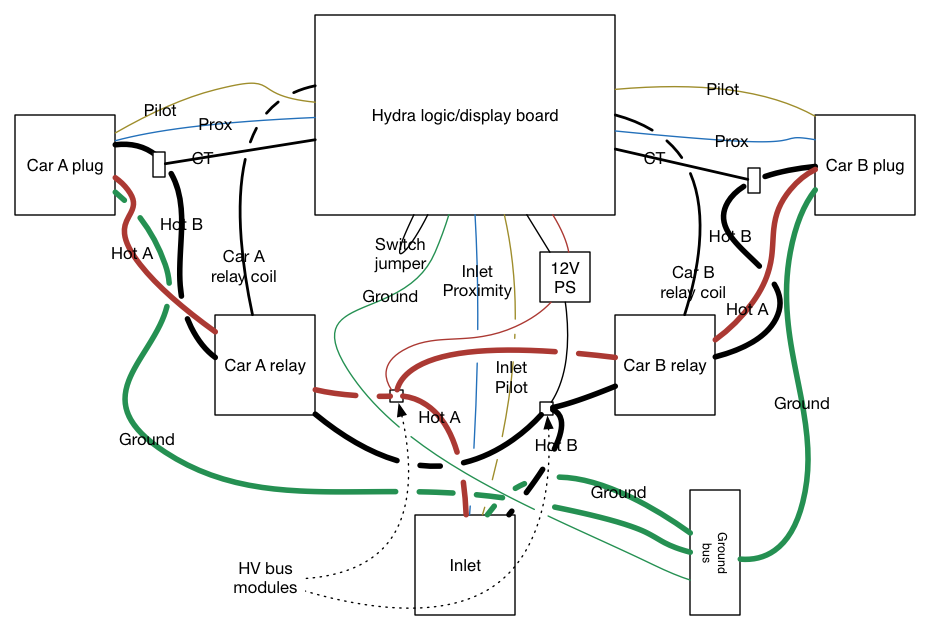 Hydra wiring diagram
The two car relays are DPST relays with 12vdc coils rated for whatever your outlet current is. They're the same kind as used for OpenEVSE. Alternatively, you can use line-powered contactors and ContactorAdapter boards, but this limits your Hydra to use on L2 EVSEs only (or, depending on your contactor coil, limits you to L1, but building an L1-only Hydra would be just silly). Fortunately, the vast majority of public charging stations are L2.
In some (most?) cases, the J1772 inlet you get will be higher rated than your plugs and cables. The software is capable of limiting the inlet current separately, but in order to take advantage of this, you must insure that your relays are wired in a "star" pattern rather than daisy-chained. In a daisy-chain, the full current of the entire system will flow through the first component's cables, limiting the design current to that capacity. If you connect each relay's supply leads together to the inlet supply at the same point, then the inlet current is allowed to be higher.
The best way to connect the inlet up with the two relays and the DC power supply is with a Cooper Bussman 16220-2 power distribution module. It has two screw terminals that can accommodate 2-14 gauge copper wire for accepting the inlet wiring, and has 8 screw terminals (four for each hot wire) for connecting to the load. It's rated at 175A, so it's plenty beefy enough.
For each relay, designate a "line" side and a "load" side. On the line side, run a wire (for 30A, use 10 gauge) from each terminal of the relay to one of the two "load" side groups of screw connectors on the power distribution bus module. Be sure that each side of the relay gets connected to a different group (corresponding to a different inlet hot line) of terminals. Be absolutely sure that you've wired one hot line and one car (load) line to each of the switches in the relay and not inadvertently wired one of the switches to connect the two hot lines together!
If you're using an internal power supply, you will also need to get "line" power into it. The minimum gauge for the bus module is 14 gauge, but for the power supply 22 gauge is sufficient. If you use smaller wire, make sure that you've made a secure mechanical and electrical connection (the concern is less safety - though a loose wire could short something out - than reliability). Do not be tempted to "piggyback" the small wire along with one of the high current wires. That might not make a firm mechanical connection, and you do not want to compromise the high-current wiring!
On the load side of each relay, connect up the hot wires of one of the J1772 cables. Run one of the hot lines through a CT coil before connecting it to the relay. Unlike OpenEVSE, you run only one of the lines through the coil, not both. It doesn't matter which one you pick. Alternatively, you can run one of the wires going from the distribution block to the line side of the relay through the ammeter coil if that's easier than using one of the J1772 cable hot lines.
Be sure that you pair up the relay coil wires with the CT coil wires along with the correct pilot and proximity lines. It doesn't matter which plug is A or B (other than car "A" being on the left side of the LCD display), but be sure that the lines for each relay coil and CT correspond to the correct pilot and proximity lines! You don't want to measure the wrong car's current draw or even worse - power up the wrong plug.
Don't forget to connect all of the grounds to a ground bus:
- The inlet ground
- Each plug/cable ground
- The inlet ground connection from the board
- Any ground connection from an internal power supply (if applicable)
Powering the Hydra (v2.0 only)
This section can potentially be considered obsolete. You can still use a "traditional" Hydra to split a single-headed EVSE installed in your home, and if you do, then powering it externally and allowing it to switch the inlet across states on demand is still a good idea. But now that the "EVSE" variant of the Hydra is an option (see Hydra_EVSE), it's probably less trouble to just build one of those to replace your single-head EVSE instead. That saves you buying an inlet, and you get to keep (or sell) your old single-head EVSE.
As of version 2.0, there are multiple possible ways to power the Hydra. In the past, the typical installation consisted of a jumper across the "switch" terminal, which would force the host EVSE into state "C" on a permanent basis. This is reasonable for a Hydra intended to be used in a public space on many different EVSEs, but on a semi-permanent installation in a home, leaving the host EVSE's contactor permanently energized may shorten the coil's lifespan, and also prevents it from displaying any charging status (it will always show a car is charging even when none is).
The problem is, if you're powering the Hydra with the AC-DC converter powered from the J1772 socket, then there's no power to the logic board when the Hydra is not asserting state C.
As an alternative, you can supply the AC-DC converter separately from an external source or - even better - supplying 12 volts from an external supply, and leave the switch terminal open. In this configuration, the Hydra will automatically transition the inlet to state C whenever one or both car relays are energized. With this configuration, the host EVSE's contactor would experience a reduced duty cycle in keeping with the original intent of the design, and you'd be able to tell by looking at it whether a car is charging or not.
The best-of-both-worlds design involves a DC input jack and a DPDT panel-mounted switch. Label the switch "Internal" and "external." Wire the Hydra's DC input jack positive pole to the common "A" pole position, and wire the internal power supply's positive output to the "A" pole "internal" side. Wire the positive pole of the external power jack to the switch "A" "external" side. Wire the switch's "B" common and "internal" contacts up to the Hydra's "switch" terminal.
Configured this way, "internal" will force the inlet permanently into state C and power the hydra from the internal AC-DC converter. Flip the switch to "external," and the hydra's logic board will be powered from an external 12 volt power supply, and the inlet will switch between states B and C on demand.
If you don't want to use a switch, then the general advice is to leave the switch terminals open if you're using external power, and short them with a jumper if you're using a 12 volt power supply powered by the inlet hot lines.
Assembling the v2.x "quick kit"
The version 2.0 Hydra board comes with all the surface mount components installed and the latest firmware preloaded. What remains is the installation of all of the through-hole components. You should find:
- The board
- An RGB backlit 2x16 character LCD module
- 2 56 ohm 1% 1/4 watt axial resistors
- A 1x18 .1" SIP header
- A 1x6 .1" SIP header
- A 1x3 .1" SIP header
- A shrouded 2x3 DIP header
- A 20k trimmer potentiometer
- 2 DC-DC converter modules, one +5v, one +/- 15v
- 3 3 point screw terminals
- 6 2 point screw terminals
- 4 2-56 1/2" nylon bolts
- 4 #4 1/4" plastic standoffs
- 4 2-56 nylon nuts
Start by installing the two DC-DC converters. The +5 volt one will have one less pin than the +/- 15 volt one. The +5 volt one goes nearest the 4.7 µF tantalum capacitor, and the +/- 15 volt one goes nearest the two voltage regulators (IC5 & IC6). The two converters must be mounted on the same side of the board as the SMD components.
Install the two CT burden resistors. They go on the same side of the board as the SMD components.
Next, install all of the screw terminals. All of them should be installed on the opposite side of the board as the surface mount components.
Install the shrouded DIP header. Pin 1 is the square one - it should be the same side as the key slot on the shrouded header. Again, this should be on the opposite side of the board as the SMD components.
Install the 3 pin SIP header for the SELECT switch. It goes on the opposite side of the board as the SMD components.
Install the 6 pin FTDI header. It goes on the opposite side of the board as the SMD components.
Install the trimmer pot. It goes on the opposite side of the board as the SMD components.
Lastly, install the LCD (this step must be last, as the LCD will cover some of the solder pads used to install the other through-hole parts). To do so, set the board on a flat surface, component-side down. Install the 18 pin SIP header, but do not solder it. Lay the LCD module on top with the SIP header mating with the interface on the module. Again, do not solder yet. Thread the 2-56 bolts through the for holes in the corner of the LCD. Place a standoff in each corner between the logic board and the LCD module and push the bolt through and thread a nut on the bottom. Tighten (but do not over tighten) each nut. When the module is physically secured in place, solder the SIP header both on the LCD module and on the logic board.
Temporarily connect a 12 volt power supply to the power terminals and adjust the contrast knob so that the text looks its best.
Now is the time to make any alterations to the jumpers on the board.
If you're using the LCD supplied with the "quick kit," then do not make any changes to the BL_COM jumper. It will have been set as appropriate for the LCD. If you're using a common cathode module, short the center and right pads (when looking at the board with the LCD connector at the top). If you're using a common anode module, short the left two pads. If you're using a common anode module, you will also need to make a small change to the Hydra sketch before updating the firmware (if it's ever necessary). If you're using the module supplied with your Quick Kit and the left jumper pair is shorted, then this change will have been made when the firmware was initially loaded.
If you are going to use FTDI programming, and have arranged for an Arduino bootloader to be programmed in your controller, then you should short the DTR_RESET jumper. Otherwise, you should leave the jumper open.
If your J1772 inlet has a 2.7k resistor between proximity and ground, then you must leave the PROX_RES jumper open. If your inlet proximity line is an open circuit to the ground wire, then you must short the PROX_RES jumper.
To short a jumper, lay a pencil soldering iron on half of both pads. Apply solder to each pad, making a small "ball" on each. Drag the iron over the two and lift straight up. If there is enough solder, a bridge will form between the two pads. Do this as quickly as possible - do not overheat the pads or you risk permanently damaging the traces.
Burden resistor calculations
If you use the CT coil specified in the chassis BOM, then you can use the burden resistors included in the quick kit and skip this section.
R14 (on Google Code) and R17 (on Google Code) must be matched to both your CT and your maximum expected outlet current. The reference design has a 30A maximum outlet current and the CT has a Te rating of 1018.
You must select the largest Rb value you can such that the maximum peak-to-peak voltage does not exceed 5 volts. Take the maximum current and divide it by Te. The maximum current is an RMS value, however, so to convert it to peak-to-peak, multiply by 2 * sqrt(2). Divide 5 by the result and select the next smaller standard resistor value. That's the value to use for R14 (on Google Code) and R17 (on Google Code). Be sure to buy precision resistors. The BOM specs 1%.
If you change the values of R14 (on Google Code) or R17 (on Google Code) and/or the CT, then you must change the CURRENT_SCALE_FACTOR constant in the code to match.
Divide Rb by Te to get volts per amp. Divide that value by (5/1024) to get units per amp. Divide 1000 by units per amp to get milliamps per unit, which is the value of CURRENT_SCALE_FACTOR.
Chassis construction
You might wish to follow along at the Hydra Illustrated Build page.
You will need:
- A Hydra "Quick kit," on which assembly has been completed
- The contents of the chassis BOM from DigiKey (2 DPST relays, 2 CT coils and a 12v 10W AC-DC converter)
- A SPST NO push button (not required if you don't need to use sequential mode)
- A J1772 inlet
- 2 J1772 cable/plug assemblies
- A case and 2 cable glands. I recommend a Polycase WC-40, a WX-42 internal mounting panel and 2 CG-16 cable glands.
- A Cooper-Bussmann 16220-2 power distribution bus module (available from http://www.grainger.com/)
- A 4 terminal ground bus (available from Home Depot)
- About 8 inches or so (each) of red and black stranded #10 copper wire (you can obtain this from trimming the J1772 cables if you wish)
- About a foot or so (each) of red and black stranded #22 copper wire
The "quick kit" is $90. The chassis BOM is around $100 + tax and shipping. A J1772 inlet is $85 from Modular EV Power and J1772 cables are $175 each from Leviton. A box and two cable glands are around $50 from Polycase. So just in parts alone, a Hydra costs close to $700.
You can, of course, build your Hydra however you like, but the formula that works best for me goes something like this:
On the WC-40, pick one of the short sides to be the "top." In the middle of this side, drill a 5/8" hole for the mode button. On the opposite short side, drill a 1 5/8" hole 1 3/8" down from the upper edge of the box (not counting the lid). Insert and center the inlet, then mark the four 1/8" holes in the corners. Once drilled, use 1/2" 6-32 bolts, nuts and lock washers to install the inlet. On the two long sides, drill a 1 1/8" hole centered on the lower "half" of the side (that is, between the short side with the inlet hole and the "rib" that runs up from the back at the center of the long side). Those two holes will be for the CG-16 cable glands.
On the WX-42 panel, use the main board as a template to mark the mounting holes. You want to center the board as best as you can. A half inch below the bottom of the board, center the two relays, and in the remaining space, mark the mounting hole for the power distribution bus module and the ground bar. Once you've marked the location for the main board, mark the two holes for the power supply module centered in the middle - the power supply will be mounted under the main board. You will be using 4 2" 4-40 M-F hex standoffs to hold the logic board over the power supply. Make sure you leave enough space for the mode button (if you're going to use one) - if the power supply is too close to the top the button may hit it and not fit properly.
Use 4 1/2" 6-32 bolts, nuts and lock washers to secure the relays. Be sure to orient the relays so that the coil tabs are nearest the logic board.
Use 4 1/4" 6-32 bolts, nuts and lock washers to secure the power distribution bus module. Positioning the bus module is an exercise in compromise. Generally the inlet wires are 6 or 8 gauge, which makes them very stiff and difficult to bend. At the same time, you must insure that the module doesn't get in the way of either the inlet or the plug cables and/or cable glands, and you must also insure that routing the load wires from the relays is not too difficult. Be sure that the mounting hardware for the bus module stays well away from the conductors and the attached wires!
Use the self-tapping screw supplied with the ground bus to secure it.
Cut four short (around 4 inches or so) #10 wires - two red, two black. Attach a QD female connector to one end of each wire. Connect a red and a black to each relay on the "line" side (this is an arbitrary choice, but should be consistent). Connect the other end of each red wire to the "red" side of the power distribution bus module. Connect the free end of the black wires to the other side. Cut a 22 gauge red and black wire approximately 8 inches long. Twist them together in a loose braid. Connect one end of each to two of the "load" terminals of the power distribution bus module, matching the colors of the wires already there. Attach the other ends to the AC inputs of the power supply module (make sure you are connecting them to the AC side!). Cut two more red and black 22 gauge wires approximately 4 inches long and make another braid. Connect one end of each wire to the DC outputs of the power supply, matching red to positive, black to negative. Connect the other end of each to the power input terminal block on the main board, matching black to ground and red to the positive terminal.
Use 2 1-3/4" 4-40 bolts, nuts and lock washers to secure the power supply. Be sure to install the wires for the power supply before installing the main board - the power supply will be inaccessible later. Use a 4-40 nut and lock washer to secure each of the 4 2" 4-40 M-F hex standoffs for the main board to the panel and use 4 1/4" 4-40 bolt to attach the main board to the standoffs.
Cut four short (around 4 inches or so) #22 black wires. Twist two into a loose braid and attach QD terminals to one end of each. Repeat for the other pair. Attach one pair's QD terminals to the coil terminals of one of the relays and the connect the other end to the relay terminals on the logic board that corresponds to the relay (that is, for Car "A"'s relay, use the "Car A" relay terminals). Repeat for the other relay. The relay terminals are not polarized (that is, it doesn't matter which terminal on the relay goes to which terminal on the board).
Connect the two current transformers to the current transformer connectors on the logic board. The coils are not polarized. Lay each CT on top of the corresponding car relay for now.
Now install the mounting plate in the chassis. You may find it easiest to remove the inlet first.
Cut the inlet hot and ground wires to length and install the two hot wires in the "line" terminals on each side of the power distribution bus module and the ground wire into the ground bus. There is no standard color code for J1772 cabling. The inlet will have three large wires and two small wires. Of the three large, one will be green or green/yellow. That is the ground wire. The other two large wires are hot lines. Each hot line is interchangeable.
Run the proximity and pilot wire from the inlet to the logic board. Using a VOM, if one of the small wires is an open circuit and the other has a resistance of 2.7 k-ohm to ground, then the open circuit is the pilot, and the other is the proximity. If both lines are open circuits, then you must close the "PROX_RES" jumper on the main board with some solder. If the ground terminal on the inlet is at "6 o'clock" and the two hot lines are at "10" and "2", then looking at the back of the inlet, proximity is at 7 o'clock and the pilot is at 5.
Run a #22 green wire from the inlet ground connector on the board to the ground bus.
Next, install each cable/plug set. First, strip around 8 inches or so of the outer jacket off of the cable. Be very careful not to nick any insulation on the inner wires. Cut and discard any packing paper or cotton that is exposed with the wires. Next, install the cable glands. Take a paper towel and dampen it with vegetable oil. Rub the first few inches of the cable with it. Remove the large cable nut from the gland, thread it over the wires. Then repeat with the gland itself. Position the gland so that about 1/4" of the outer jacket protrudes inside. Securely attach the outer nut to the gland. Pass the wires through the box and thread the chassis nut for the gland over them. Install the gland in the chassis and secure it with the chassis nut.
Again, there is no standard color code for the plug wires. Three of them will be markedly larger, and one of those three will be green or green/yellow. That is the ground, and the other two are the AC hot lines. It doesn't matter which hot line is which - both are interchangeable. If there is only one small wire, it will be the pilot. If there are two, then use an ohmmeter to measure the resistance from each to ground. One will be an open circuit, the other will have a resistance that changes as you push the latch button on the plug. The open circuit is the pilot, the other is the proximity.
Attach QD female connectors on the #10 red and black wires (the hot lines). Pass one of the hot lines of each plug through the respective current transformer (it doesn't matter which, but do NOT pass both lines through), and then connect each hot line to one of the two relays on the "load" side. Connect the ground cable to the ground bus. Connect the pilot line and the proximity line (if available) to the respective connectors on the main board. If your plugs do not supply a proximity line, then just leave the proximity terminals empty.
Be sure that each car plug's hot lines both go to a single relay's "load" terminals and that the corresponding relay coil wires, current transformer wires and pilot and proximity wires all, as a group, go to the same "car" side of the logic board. You do not want to turn the wrong car's power on!
Carefully tuck all of the wires down out of the way and attach the lid.
Testing
For your first use of the Hydra, you should attach a single car to each plug and charge at the maximum charge rate you anticipate using for a half hour. Watch very closely during the first few minutes for any evidence of heating on any of the high current wiring. If your connections are improperly crimped, the high resistance will result in heat damage. After a half an hour, disconnect the power and quickly open the case and check all of the wiring for any signs of elevated temperature. You can expect the wiring to be above room temperature, but if it's too hot to touch, then that's a sign of trouble.
You should periodically inspect the Hydra for signs of heating and repeat the above test.
Do not attempt to reuse heat-damaged components.
At 30 amps, a resistance of a mere tenth of an ohm will result in 90 watts of power loss, most of which will be converted to heat. Thats three times as much power as the soldering iron you probably used to assemble the kit!
Firmware details
The firmware depends on the LiquidTWI2 library to drive the LCD, and the PWM library to support altering the PWM frequency on the digital pins so that they can be used to drive the pilot outputs.
Theory of Operation
Host EVSE signals
The incoming pilot wire from the host EVSE goes through D3 (as required by the spec) and R5 (on Google Code). Those two components are sufficient to transition the host EVSE to state B, but unfortunately no power is supplied by the EVSE until and unless a transition to state C occurs. R6 (on Google Code) and the power switch accomplish this. In most cases, merely jumping the power switch permanently is acceptable. If your EVSE does not tolerate jumping directly to state C, then you must manually engage state C with a switch.
The pilot, fresh from D3, also arrives at the non-inverting input to IC1A. The inverting input is set with a voltage divider to 1 volt. Thus, when the incoming pilot is more than 1 volt, the output of the comparator will be high (thanks to pull-up resistor R30 (on Google Code)). The pilot must be compared to a non-zero voltage because D3 prevents us from seeing the negative portion of the pilot signal (which we wouldn't want to present to the comparator anyway).
The proximity line is scaled (as per the spec) with R7 (on Google Code) and R8 (on Google Code) (which is either on the board or installed on the inlet itself). The conditioned proximity signal is fed to the inverting input. The voltage divider on the non-inverting input is set for 2 volts. The specification says that when the handle is fully connected it should be 1.5 volts and 3 volts when the button is pressed. The comparator output (pulled up by R31 (on Google Code)) will be low whenever the proximity pin is less than 2 volts. This means that the proximity circuit is in the 'ready' state.
Outgoing EV signal handling
Versions < 2.2
Pilot generation requires a bipolar 12 vdc power supply. This is created with DC1. R18 (on Google Code) and R19 (on Google Code) provide a minimal load for the converter, as the pilot generation circuitry alone is not a large enough load. The two voltages are fed into IC3.
The two non-inverting inputs of IC3 are fed with a single voltage divider for 2.5 volts (really it just needs to distinguish between high and low logic levels from the controller).
Versions >= 2.2
Pilot generation starts with a +/- 15 volt DC-DC converter. The output is fed into the V+ and V- of a DG303 2xSPDT analog switch IC. The +15V is also fed into a 7812 12 volt regulator, and -15V is fed into a 7912 -12 volt regulator. The regulated outputs are fed into the actual switch terminals of the IC. Each SPDT switch is actually made of a pair of SPST switches both controlled by a common logic input, but with each switch control inverted from the other. Each switch has a separate input and output pin. To form a SPDT switch, the two output lines are joined together, forming the output.
Common
The output of the pilot generator is fed through a 1K resistor (per spec) and sent to the car.
The output pilot signal is also fed into a scaling and voltage divider network to convert the -12 to +12 volt signal into an approximate 0 to 5 volt range. This is in turn fed into one of the analog read pins on the controller. This allows the firmware to detect transition changes on the pilot pins.
When the host EVSE inlet has a proximity transition, that must be passed along to the vehicles, as the specification calls only calls for a rapid response to proximity transitions, not pilot changes. It's desirable to insure that all load is removed before the host EVSE plug is pulled.
To accomplish this, the controller has a single outlet proximity signal. R34 (on Google Code) and Q3 form an open collector for this signal. R35 (on Google Code)'s value is such that the proximity value seen by the EV is just under 4 volts, which should be sufficient for the vehicle to see a transition. D8 and D9 are used to prevent the proximity signal from one car from affecting the other car under normal conditions.
Ammeters
Each current transformer acts as an AC current source. R14 (on Google Code) and R17 (on Google Code) are burden resistors that convert the current into a voltage, which the ADCs can interpret. One of the legs of the CT is anchored to 2.5 volts (with the voltage dividers R12 (on Google Code) & R13 (on Google Code), and R15 (on Google Code) & R16 (on Google Code)). The burden resistors are intended to provide a peak-to-peak maximum voltage of 5 volts. R33 (on Google Code) and D4 & D5 (and R32 (on Google Code), D6 & D7) form a clamp to protect the controller from excessive excursions.
Relays
The relay outputs are fed from fairly standard open collector circuits (R2 (on Google Code) & Q1; R1 (on Google Code) & Q2). D1 and D2 protect the transistors from coil collapse voltages. Each relay simply acts as an on-off switch, connecting or disconnecting the two hot lines of the car in question to the hot lines of the inlet.
Controller
The controller is fused for external crystal timing, and a 16 MHz crystal is chosen to be compatible with the Arduino IDE. The ISP programming pins (including /RESET) are connected to an ISP header. Those pins are not shared with other functions. The i2c bus is connected to an i2c GPIO chip wired to the LCD display. The async serial pins are brought out to an FTDI connector. DTR on the FTDI connector is connected to /RESET through a capacitor and the DTR_RESET jumper so that DTR transitions can reset the CPU if the jumper is closed. If you load an Arduino style bootloader, then programming can be done with an FTDI cable instead of an ISP cable. Alternatively, since 5 volts is supplied to the FTDI cable, it can power external serially connected devices (about 100 mA of spare 5 volt capacity is available).
DC-DC converter DC2 converts the incoming 12 volt power into 5 volts for the controller and the rest of the logic system.
Troubleshooting
Step 1 of troubleshooting the Hydra is removing the board from the chassis and disconnecting all of the wiring. If you have an ISP programmer capable of supplying 5 volt power, connect it up and observe the display. If you see nothing at all, then try adjusting the LCD contrast. If that doesn't work, then your LCD is not getting power.
If you see a row of filled-in boxes on the top line of the LCD and nothing on the bottom, then the LCD is getting power, but either the controller is not running or the path between the controller and the i2c GPIO chip and/or the LCD is not functioning properly.
If you see nothing on the LCD, but you do see the backlight start white, pause for a couple seconds, then turn red, then adjust the LCD contrast. If that doesn't work, then either the LCD contrast voltage is not getting to the LCD or the LCD is not getting power (other than on the backlight pins).
If you see garbage on the LCD, but the backlight is working, then check the data and control logic pins between the i2c GPIO chip and the LCD.
If you see the Hydra boot banner and version with a white backlight, and then a "DISCONNECTING" error in red, then the board is functioning properly. Connect a wire between the first and third screws on the inlet pilot/proximity terminal and you should see the backlight turn yellow and the display indicate that the inlet is "PAUSED." This all means that your board is functioning properly.
If you cannot program your Hydra, check to make sure the crystal and its two loading caps are installed properly. This is particularly true if the fusing (in the Arduino IDE the "burn bootloader" step) succeeded, but subsequent programming fails. Once the ATMega controller is fused for a crystal, the crystal must be connected in order for the chip to work at all.
If the board works out-of-circuit, then the remaining troubleshooting is fairly straightforward. If the board won't power up with 12 volts on the 12 volt input terminals, then check the 5V DC-DC conversion module and its associated components.
If you have access to an EV simulator, then use it on each car plug to check that the different states are discovered properly. If it's an EV Sim Mark II, then you can also check that the outgoing pilot for each car is correct.
If while a car is connected and charging the display consistently shows 0 mA of current draw, then check the current transformer coil(s) to make sure that they're connected properly and that only ONE hot wire (and it must be a hot wire) from each car (and it must be the correct car) passes through each CT. If that's not it, then check the associated ammeter components on the board.
If neither car's pilot is being generated properly, check the +/- 12 volt regulated power supplies. If they're incorrect, check the associated output of the +/- 15 volt DC-DC converter to make sure it's correct. If the +/-12 volt power is correct, check the switch chip and the pilot output impedance resistors.
If the inlet pilot and/or proximity are not recognized properly, check to make sure the ground terminal on the inlet block is connected to the main ground bus. The board, each plug and the inlet must share a common ground. For safety, the path between either plug's ground and the inlet ground must be constructed for minimum resistance and appropriate current carrying capacity.
If the Hydra gets hot during use stop using it immediately and check the high current wiring for heat damage. Do not use or attempt to reuse heat damaged components. The wiring is expected to be warmer than ambient temperature, but it must never be allowed to heat up higher than the temperature rating of any of the wires, their insulation or any of the component specifications along the high-current paths. If it is too hot to comfortably touch, then it is too hot.
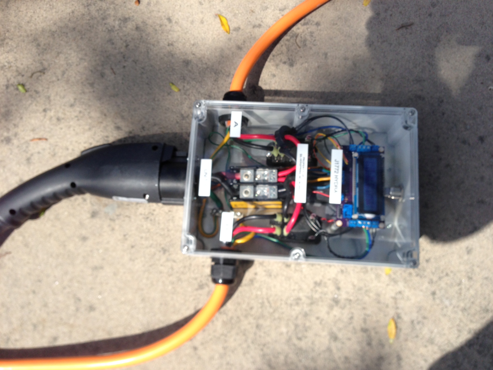
Images
 The 2.0 board fully assembled, back view.
 The 2.0 board fully assembled, top view.
The connectors, right side, top to bottom:
- Relay for car B
- J1772 for car B - top to bottom: proximity, pilot, ground
- Current transformer for car B
The bottom, left to right:
- LCD contrast knob
- SELECT switch connector
- power switch (just below the SELECT switch)
- J1772 inlet - left to right: ground, pilot, proximity
- 12 VDC power input
- ISP connector
- FTDI serial connector (just below the ISP)
The left, top to bottom:
- Relay for car A
- J1772 for car A - top to bottom: ground, pilot, proximity
- Current transformer for car A
Board version history
- 0.5 - initial version
- 0.9 - Attempted correction for DC-DC pad spacing (still wrong), added resistor before zener clamp in ammeters.
- 1.0 - Corrected DC-DC pad spacing, added FTDI connector (but with RX and TX backwards).
- 1.3 - Corrected FTDI connector, reverted to 6 pin DC-DC pads for CUI modules. Switch from 2N2222 transistors to 2N4401 for relay drivers. Added outgoing proximity circuitry. This version contained a major error causing the +5 v supply to be shorted to ground.
- 1.4 - Corrected short circuit in v1.3.
- 1.5 - Added bypass cap to CT anchor - improves low current ammeter accuracy.
- 1.6 - Rearranged the connectors. Car A is now on the left side, car B on the right, and the inlet is on the bottom.
- 2.0 - Surface mount design. Integrated RGB LCD. Inlet state control transistor (alternate power system).
- 2.1 - Slight component rearrangement. Added TVS diode across inlet proximity line. Relabel car A and car B to swap them - the board is intended to be mounted component-side down.
- 2.2 - Replaced the op amp based pilot generation circuitry with analog switch based system.
Currently, 2.2 is the recommended version.
Links
- My online store for boards and kits
- PDF of v2.2 board schematic
- Eagle SCH file for v2.2 board
- Eagle BRD file for v2.2 board
- DigiKey Chassis BOM for the Hydra
- Software repository for the Hydra
- PWM library
- LiquidTWI2 library
- OSHPark store for Hydra boards
- the Hydra Illustrated Build
- HydraCourtesyNote - a page to share when using the Hydra in public