Assembling the OpenEVSE Plus (V2) Kit - gorawen/open_evse GitHub Wiki
Assembling the Open EVSE Plus (V2) kit
This guide is intended to show non-EE people what to do after their Open EVSE Plus kit arrives in the mail. It is not intended to be a complete course in how to be an electronics technician, but will show a few tips that will be helpful in completing a successful project.
Gather tools
These are the tools I found useful. You may find other tools that work just as well
- Standard soldering iron
- Fine rosin core solder (.020 - .030 diameter)
- Needle-nose & standard pliers
- #2, #1, #0, #00 phillips screwdrivers
- Small flat screwdriver
- Cordless drill with standard drill bit set
- Utility knife
- Wire strippers
- High-speed rotary tool such as Dremel
- 1/8 inch carbide burr for rotary tool
- Small flat file

Gather Required parts
These are the parts I used. You are welcome to customize your own with different parts.
Most of these parts are available at your local Home Depot, Lowes, or auto parts store. See other Open EVSE Wiki pages for some online sources. I noted where I bought mine in parenthesis below.
- Open EVSE Plus (V2) Kit w/ RGBLCD
-- If you order the "Built and Tested" version, you can skip a few assembly steps. You will still need all these additional parts to make it useful!
- Insulated 1/4 inch female spade connectors for 10 AWG & 18 AWG (HD)
- Assorted heat-shrink tubing (HD)
- 30 amp relay w/12V coil (DigiKey)
- GFI current coil (DigiKey)
- 20-22 AWG wire (Radio Shack)
- Suitable enclosure box: 4x4 would work, I used 6x6 and had plenty of space. (HD)
- EVSE charging cord (Leviton)
- 3-foot 12/3 cord (HD)
- 6L-20 plug (HD) NOTE: Choose whatever cord/plug is convenient for your needs.
- Grounding block w/ min 3 lugs
- #4-40 x 3/4-inch screws (HD)
- #6-32 x 1/2 inch screws (HD)
- 1/4 x 1/4 plastic spacers x4 (HD)
- 1/4 x 1/2 plastic spacers x4 (HD)

Assembling the PCB Kit
You need some basic soldering skills, but the really touchy stuff is already done for you. If you've never soldered components to a PCB, please take a moment to Google for some tutorials. I'm not going to repeat that valuable data here.

The PCB through-hole components should be installed over the printed areas outlining each component. It's hard to mess this up, but please refer to the photos for guidance. Remember to install the shortest components first so you can let gravity hold the items in place while you solder the pins that stick through the holes. You will be soldering on the same side of the PCB as the surface-mount components so be very careful not to touch existing components with the soldering iron. Use a pointed iron bit and touch it to both the protruding pin and the copper pad around the hole. Touch the solder to the other side of the pin and wait for the pin to heat up enough that the solder melts into it. DO NOT melt the solder by touching it to the iron. This will result in poor adhesion and possibly failed connections. It is critical that the pin and copper both get hot enough to melt the solder, but don't overdo it or the component being soldered could be damaged.
Refer to this page for more details on assembling the PCB parts: http://code.google.com/p/open-evse/wiki/OpenEVSE_Plus_spec
A note about electrical connections
I am not a fan of crimp connectors. Unless they are precisely crimped by quality crimping tools, you are likely to get somewhat less than perfect electrical continuity. Considering how easy it is to apply a dab of solder and get outstanding electrical contact with almost no chance of working loose or having a high resistance joint, I HIGHLY recommend leaving the crimper in the tool box. These photos shows a simple technique for connecting wires to crimp terminals with solder. Make a cut around the insulation with a utility knife to weaken the plastic, then twist it off with pliers. Don't try to cut the plastic completely with the knife. Just score it and then break it with the pliers. Notice the little loop that slips inside with a bit of tension to hold it all together until the solder flows in. Be sure to use enough solder to completely fill the inside of the crimp barrel.

These connections are then covered in two layers of heat shrink tubing. This is where multiple heat shrink sizes comes in handy.

Assemble the RGB LCD and shield
The LCD comes as a small kit containing a shield board, the LCD board, a pin header, 4 plastic spacers, and a jumper wire. The following photos show how to assemble them.
 Notice that the angled 4-pin header points away from the surface mount component. If you do it the other way, it will interfere.
IMPORTANT NOTE: Remember the little component labelled "VR-1" in the lower left corner of this picture. You will need to turn that with a tiny screwdriver after the project is complete to set the display brightness the first time you power up your EVSE.
Notice that the angled 4-pin header points away from the surface mount component. If you do it the other way, it will interfere.
IMPORTANT NOTE: Remember the little component labelled "VR-1" in the lower left corner of this picture. You will need to turn that with a tiny screwdriver after the project is complete to set the display brightness the first time you power up your EVSE.

I accidentally provided a good example of proper and improper soldering in the photo above. Notice that the 7th and 8th pins don't have much solder around them. They make electrical contact OK, but the 9th and 10th pins are what they all should look like.
Once the headers are soldered to the shield board, place the LCD board over the header row as shown below. Be sure to place the 4 plastic spacers at each corner prior to soldering the pins!

In order to use the control button, you need to solder two wires into the shield board. Connect one to any of the 5 ground pads and the other to the "S" pad.

At some point, you need to decide how to mount the display so that it will be visible. If you are using a clear lid on your box, you can mount it inside. I chose a solid box which requires measuring and cutting a hole.

I made a rough cut with a carbide burr in a dremel tool, then cleaned it up with a flat file. Don't drill the holes until the square hole is finished. That way you can use the circuit board as a drill guide while the LCD holds it all perfectly aligned.

Once everything is cut out, attach the LCD to the lid with #4-40 screws. For mine, 3/4 inch screws ended up being exactly the right length with no trimming required. Please note: I goofed up in this picture and installed the display 180 degrees off. I fixed it later, but you should avoid my mistake. The 4-pin header should have been pointing toward the middle of the lid, not the edge.

The button I used came from Radio Shack and is intended for mounting in a thin piece of sheet metal with a lock washer and nut. I found that drilling a 7/64 inch hole in the plastic allowed the threads to bite in just perfect so that the nut was not needed. I had to use pliers to screw the switch into the hole.

By bending the switch prongs apart a little, it was easy to solder the wires from the LCD onto them. You can easily see the small pieces of heat shrink waiting to cover the solder joints. You can't really see the medium sized heat shrink behind them that will cover both of the smaller ones. Be sure to put them in place before soldering or you will have to unsolder those new connections.

Finally, the lid is complete!

My next step was to fix the 180 degree rotation error, but you shouldn't have to do that since I warned you above.
Mounting components in the box
Now it's time to mount the EVSE brain board to the plastic box. Figure out where you want it inside and mark the holes. I put mine dead center, but if I do it again I'll offset it a bit to leave more room for the relay. Just be sure that wherever you end up putting it, you can insert the control wires into the blue headers. Mark the holes very carefully and drill them out to 1/8 inch. From the OUTSIDE of the box, enlarge the holes to 1/4 inch, but be careful not to drill all the way through. This will create a stepped hole pocket to recess a nut into. In the following picture, I have the hole on the right ready to take the nut and the hole on the left is just drilled to 1/8 inch.

The #4-40 nuts are just slightly too large to drop into the holes, but a little heat from the soldering iron will melt them right into place and create a solid self-holding nut that appears cast into the case.

Use the same technique with the #6-32 bolts and nuts for the relay, except use a 9/32 bit to enlarge the holes. I ended up having to cut off excess bolt length to prevent protrusion.

Mount the brain board using the 1/4 x 1/2 plastic spacers to keep it suspended above the floor of the box.

I decided not to utilize a fuse holder in my EVSE because it is connected to a dedicated circuit with a 20 amp circuit breaker. It seems redundant to also put fuses in the EVSE box. If you plan on connecting to unknown circuits of opportunity, please consider adding the fuses as shown in some of the other EVSEs featured on this website. I also decided to not piggyback my power and test leads into the big spade terminals as some other builders did. Instead, I bought piggyback (AKA "Cheater") adaptors that allow plugging in two female terminals on each male prong of the relay.

Once its all assembled, each wire has its own terminal.
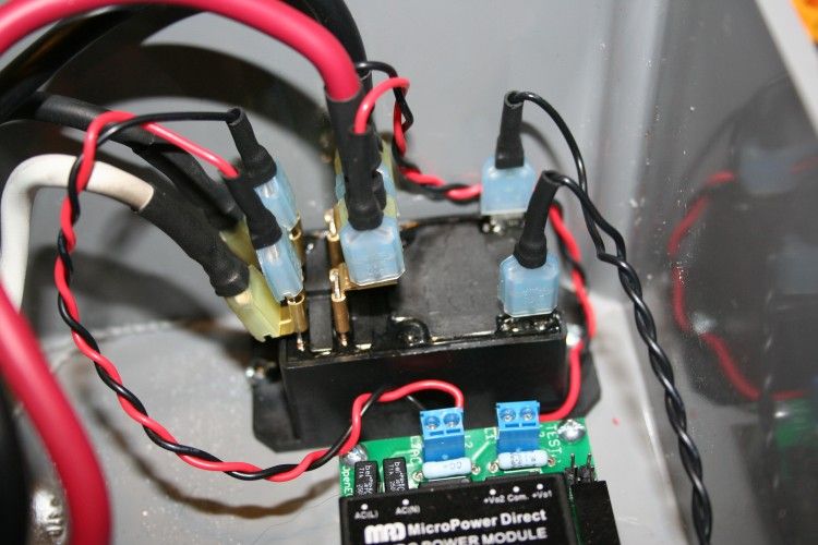
You can't really see it in this picture, but the CT coil leads are the only thing soldered to header pins on the brain board. Next time, I will use a plug-in jumper to make a cleaner installation. The CT coil goes over the red and black wires of the J1772 cable. The blue wire doesn't connect to anything and the orange wire connects to the Pilot output. Be sure to run a ground wire (my little green wire) from the grounding bus to the ground port on the EVSE brain board.

The last thing to do is connect the 4-wire jumper from the EVSE board to the LCD board and close it all up. Be sure to run ground to ground. It is possible to plug the jumper in backwards and that would be a bad thing. The ground pins are on the right in this picture.

When it's all closed up, the button is easily operated and looks nice just below the LCD.

Put it to work
SAFETY NOTE: Whether you plug it in or hard wire it directly to a junction box, remember is that this box is pulling a lot more power through it than your average toaster. Excellent quality connections are vital. If there is any doubt about the quality of the outlet or the feeder wires, replace them. You could burn down your house by using inadequate or worn components!
The first time you power on the EVSE, it is likely that the screen will show nothing. This is normal. Open the cover without disconnecting the colorful ribbon cable from the display and find that little component on the back of the display labelled "VR-1". I was able to turn it by simply pressing my finger against it and rotating my hand, but you might need to use a tiny screwdriver. Turn it until the display looks right. This should be a one-time adjustment, but feel free to experiment with different levels if you decide it isn't just right.
The next gotcha that I experienced was no button response. Again, this is normal with firmware 1.0.5 that shipped on my board. This is because Chris disabled the button in order to work around a bug that causes the system to freeze when an LCD is not plugged in. I'm working on figuring out how to have a universal auto-detect in the code, but in the meantime you will need to reload firmware to fix this.