Adafruit RGB Display - gorawen/open_evse GitHub Wiki
Adafruit RGB LCD
by mwolrich updated by chris1howell
Adding the optional Adafruit RGB display requires basic soldering skills to assemble the kit. The kit is avaliable from Adafruit in 2 versions either works fine:
https://www.adafruit.com/products/714
https://www.adafruit.com/products/716
Follow the assembly directions (note exception below) on the Adafruit site here: http://ladyada.net/make/rgblcdshield/
Note - The Adruino stacking .1" pins are not reccomended if using the standard OpenEVSE board. Install the pins to stack with the OpenEVSE Arduino shield kit.
Hardware
A 4-pin header is installed by default on the standard OpenEVSE PCB, The pins are lableled GND - 5V - A5/SCL - A4/SDA.
Wires can be soldered directly, wire wrapped or by using a 4 pin .1" Jumper. Soldering the jumper wires to the Adafruit RGB LCD and connecting to the OpenEVSE with the 4 pin jumper connector works very well and allows for easy disconnection. https://www.sparkfun.com/products/10374
Connect the +5 to the +5 on the LCD shield (3rd pin from the right end bottom, when viewed from the bottom), then connect the GND from the OpenEVSE to the GND on the Adafruit (4th pin from the right end bottom).
Then connect A5 on the OpenEVSE to A5 on the shield (leftmost pin on the bottom), and finally connect A4 to A4 on the shield (2nd pin from the left bottom)

NOTE: The Adafruit display has non-connecting grounds. Connect the two adjacent ground pins together. (if you don't do this, the display will not light up).

Then connect A5 on the OpenEVSE to A5 on the shield (leftmost pin on the bottom), and finally connect A4 to A4 on the shield (2nd pin from the left bottom)
Firmware
The current firmware containd all the code required to run the Adafruit RGB display. By default standard boards are shipped with the code enabled.
Wiring Connected AdaFruit RGB LCD PCB

Wiring Connected OpenEVSE PCB


EVSE Not Connected

EVSE Waiting

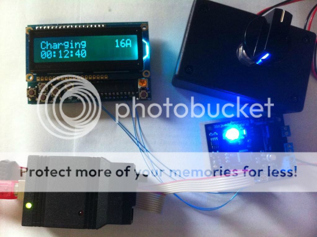
EVSE Charging
EVSE Vent Required

EVSE Diode Chk Failed
