Wiring Limit Switches - gnea/grbl GitHub Wiki
The limit switches are used to detect the physical limits of the working area and to position the head in initial position during the homing process. Properly connected limit switches can increase significantly the reliability of the GRBL - the microcontroller pins connected to the switches are very vulnerable to any noise.
Before starting, make sure your coordinate frame is setup properly on your CNC machine and satisfies the right-hand rule. If you're not sure, its explained in the quick setup guide here. Otherwise, you will likely encounter problems with the homing cycle, where it behaves strangely. If you are having issues with the homing cycle, read this FAQ.
There are two types of end switches wiring:
-
Normally Opened end switches (NO) - switches are connected in parallel, if the head hits one of the switches the resistance becomes low (<10 Ohm). The wiring is simple but there is no indication if one of the switches is disconnected (broken wire).
-
Normally Closed end switches (NC) - switches are connected in serial, if the head hits one of the switches the resistance become high (> 1 MOhm). The wiring is more complicated but if any of the switches is disconnected (broken wire) this will be immediately detected. This is the way how all professional CNC machines end switches were wired.
The easiest way to attach limit switches to Arduino UNO is to just connect the switches to the corresponding pins and to rely on the internal weak pull up resistors (~47K) of the ATMega328 chip. The Normal connected (NC) switch wiring is shown below:

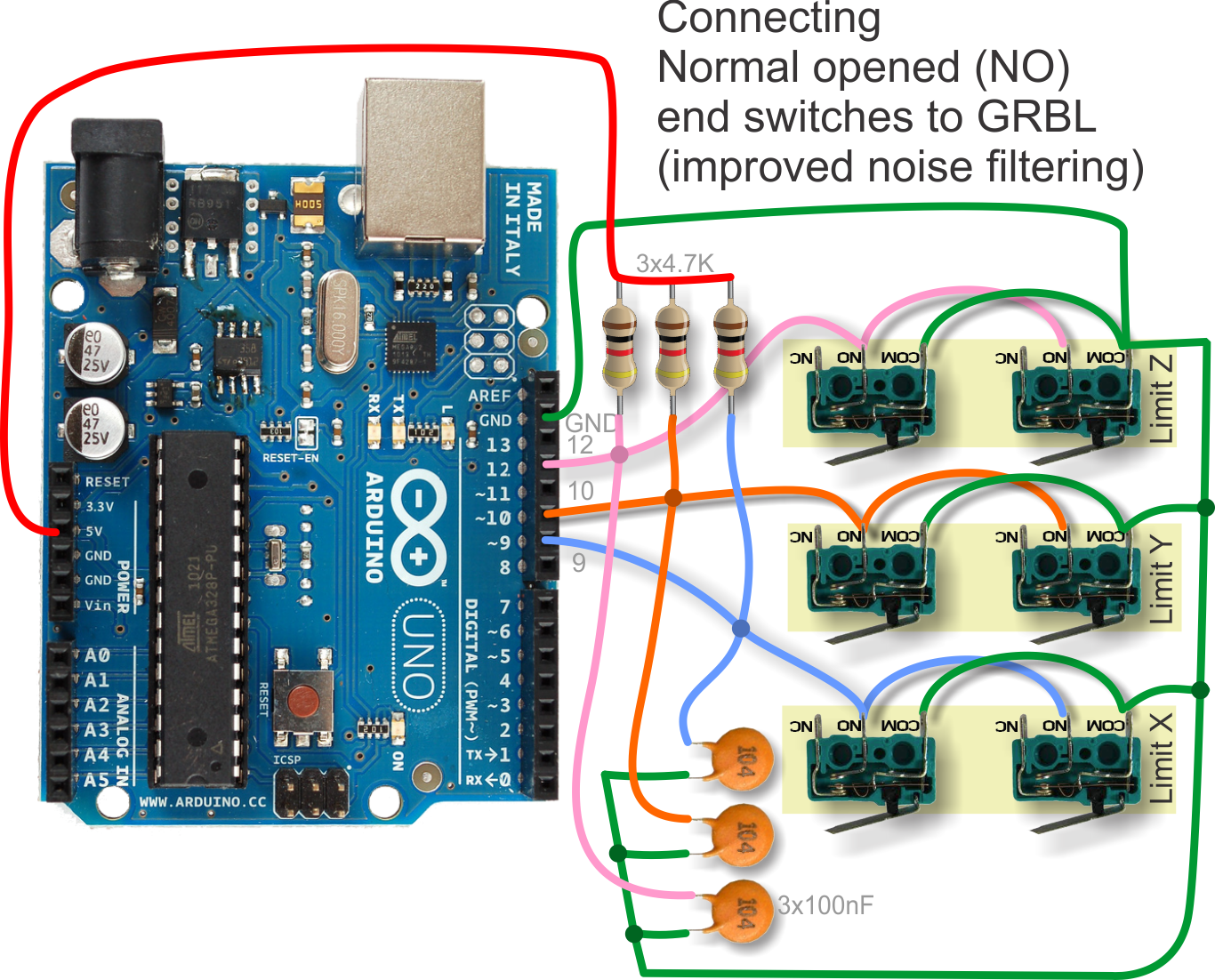
The Normal Open (NO) switch wiring is shown below:

One improvement is to connect 1K to 4.7K pull up resistors to 5V and 100nF capacitors to GND. The extra pull ups and capacitors have noticeable noise suppression effect over the GRBL performance.

Adding shielded cables to the end sensors or at least using twisted pair of two wires reduces further the noises injected from the next door stepper motor cables.
The ultimate solution for noise filtering on end switches is to add optocouplers - they have many benefits compared to the listed above solutions:
- There is no direct galvanic connection between the end sensor and the microcontroller pin - any ESD discharges will not affect the GRBL controller
- Optocouplers are inert elements - short glitches will simply not pass at all
- Optocouplers are current driven elements and they require huge energy from the noises in order to pass - in normal operating conditions they effectively cut all the noises
If you're building a two-axis system, such as a laser engraver or pen plotter, you may also wish to read the limit switch section of the Two-Axis System Considerations page.
During the discussion on GRBL forum we came to the following design of GRBL limit switch end sensor break out board - see the images below. The board is single side PCB (1.0mm to 1.6mm FR4) and uses connector with screws for attaching the end sensor wires. We recommend to use crimping of the wires before inserting them into the connectors.
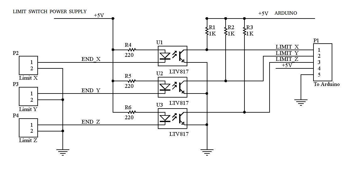
The schematic of the end sensor board which uses optocouplers
The LIMIT SWITCH side and the ARDUINO side should use 2 different isolated power supply to take real advantage of the opto isolation.
BEST
OK

The BOM file of used components and the estimated price of the board

The 3D view of the board - this is how it will look like after assembly.

The bottom copper layer (viewed from top side of the board)

The top silkscreen layer (viewed from top side of the board)

The bottom solder resist layer (viewed from top side of the board)

The DXF file of the copper layer (view from bottom - ready for milling) GRBL.DXF.V2.zip
The GCode generated in CopperCam for milling the board - by having some CNC and engraving bit it's possible to mill the board from FR4.
The gerber files and the NC drill files for producing properly the PCB (you can send these files to any PCB factory to get good quality boards).
The schematic/BOM/PCBs and other layer images as single PDF for convenient documentation
End.switches.break.out.board.pdf
For Woodpecker PCB the wiring of end switches should be done in the following way:

for Woodpecker PCB v3.4 (the black one) : Silkscreen labels for X and Z limit switches on newly released (actually january 2020)Woodpecker 3.4 CNC control board appear to be wrong ( reversed )
You can use some cable housing and crimp the wires to get more professional look (these housing connectors will fit straight into the board header)
http://uk.farnell.com/multicomp/2226a-02/crimp-housing-1-row-2-way/dp/1593506
Normally-Closed (NC) vs Normally-Open (NO) switches
This is the way how all professional CNC machines end switches were wired.
Here's why:
Use NC switches. Because whenever switches fail, the failure mode is ALWAYS "open" or "fails to make contact". Simple fact of nature, it's just the way things are.
Assuming a NO switch is used..... While homing in on a defective switch, you will not know that the switch is malfunctioning, not until after you have crashed your machine. If the switch fails to make contact then the machine crashes.
Assuming a NC switch is used..... If the switch is bad (in this case the contacts will be open), then no homing occurs, GRBL will return an error and homing does not proceed, and your machine doesn't crash.
So it does make a BIG difference which switch contact configuration you use for limit switches, NC or NO. Crash or no crash.
Capacitors for noise filtering
Even if you do use NC contacts, you still need those 104 (0.1uF) capacitors, as close to the Arduino as you can place them. You can argue all day that those caps won't make a difference since the caps are shorted out by the switches. The explanation for this phenomenon is quite long but the first power line glitch will convince you otherwise. (Plug in your blender next to the CNC's AC plug and turn it on. Your CNC should still behave normally despite the blender.)
Side benefit: With NC switches, the connection is broken cleanly when you hit home position, therefore no contact bounce occurs. (Contact bounce occurs only during switch closure, NOT during switch opening.)