Edge Triggered Interrupts - glennlopez/EmbeddedSystems.Playground GitHub Wiki
NVIC (Nested Vectored Interrupt Controller): is found in every Cortex-M based micro controller. They allow for some very flexible ISRs (rather than having polled interrupts, you may want to have many small ISR's each with specific sources of interrupts interrupting each other based on priority). Find out more about NVIC's at http://www.keil.com/support/man/docs/gsac/gsac_nvic.htm
Address definitions
Note: The example on this page illustrates how you can use an edge triggered interrupt to monitor/count how many times a switch (PF4) has been pressed. The example code will increment a variable labelled "FallingEdges" anytime an interrupt trigger is invoked. A breakdown of the registers used in the example is listed below.
// NVIC Registers
#define NVIC_EN0_R              (*((volatile unsigned long *)0xE000E100))  // IRQ 0 to 31 Set Enable Register
#define NVIC_PRI7_R             (*((volatile unsigned long *)0xE000E41C))  // IRQ 28 to 31 Priority Register

// Standard GPIO Port Registers
#define GPIO_PORTF_DIR_R        (*((volatile unsigned long *)0x40025400))
#define GPIO_PORTF_AFSEL_R      (*((volatile unsigned long *)0x40025420))
#define GPIO_PORTF_PUR_R        (*((volatile unsigned long *)0x40025510))
#define GPIO_PORTF_PDR_R        (*((volatile unsigned long *)0x40025514))
#define GPIO_PORTF_DEN_R        (*((volatile unsigned long *)0x4002551C))
#define GPIO_PORTF_AMSEL_R      (*((volatile unsigned long *)0x40025528))
#define GPIO_PORTF_PCTL_R       (*((volatile unsigned long *)0x4002552C))

// GPIO Port Interrupt Registers
#define GPIO_PORTF_IS_R         (*((volatile unsigned long *)0x40025404))
#define GPIO_PORTF_IBE_R        (*((volatile unsigned long *)0x40025408))
#define GPIO_PORTF_IEV_R        (*((volatile unsigned long *)0x4002540C))
#define GPIO_PORTF_IM_R         (*((volatile unsigned long *)0x40025410))
#define GPIO_PORTF_RIS_R        (*((volatile unsigned long *)0x40025414))
#define GPIO_PORTF_ICR_R        (*((volatile unsigned long *)0x4002541C))

// Clock Gating Registers
#define SYSCTL_RCGC2_R          (*((volatile unsigned long *)0x400FE108))
Core Peripherals Base Address: 0xE000.E000
- Nested Vectored Interrupt Controller Registers (pg 132)
- EN0: 0x100 - Interrupt 0-31 Set Enable
- PRI7: 0x41C - Interrupt 28-31 Priority
GPIO PORTF (APB) Base Address: 0x4002.5000
-
Port Configuration Offsets (pg 657)
- GPIODIR: 0x400 - Direction
- GPIOAFSEL: 0x420 - Alternate Function Select
- GPIOPUR: 0x510 - Pull-Up Select
- GPIOPDR: 0x514 - Pull-Down Select
- GPIODEN: 0x51C - Digital Enable
- GPIOAMSEL: 0x528 - Analog Mode Select
- GPIOPCTL: 0x52C - Port Control
-
Edge Triggering Offsets (pg 657)
- GPIOIS: 0x404 - Interrupt Sense
- GPIOIBE: 0x408 - Interrupt Both Edges
- GPIOIEV: 0x40C - Interrupt Event
- GPIOIM: 0x410 - Interrupt Mask
- GPIORIS: 0x414 - Raw Interrupt Status
- GPIOICR: 0x41C - Interrupt Clear
System Control Registers Base Address: 0x400F.E000
- System Control Legacy Registers (pg 234)
- RCGC2: 0x108 - Clock Gating Control Register 2
Port Initialization
Some C monikers will be used in the steps below. If you are not familiar with what setting, clearing, or toggling bits are, you can read about them at https://en.wikipedia.org/wiki/Bit_manipulation
void EdgeCounter_Init(void){
  SYSCTL_RCGC2_R 		|= 	0x00000020;     // (a) activate clock for port F
  FallingEdges 			 = 	0;              // (b) initialize counter

  GPIO_PORTF_DIR_R 		&= 	~0x10;    		// (c) make PF4 in (built-in button)
  GPIO_PORTF_AFSEL_R 	&= 	~0x10;  		//     disable alt funct on PF4
  GPIO_PORTF_DEN_R 		|= 	0x10;     		//     enable digital I/O on PF4
  GPIO_PORTF_PCTL_R 	&= 	~0x000F0000; 	// configure PF4 as GPIO
  GPIO_PORTF_AMSEL_R 	 = 	0;       		//     disable analog functionality on PF
  GPIO_PORTF_PUR_R 		|= 	0x10;     		//     enable weak pull-up on PF4

  GPIO_PORTF_IS_R 		&= 	~0x10;     		// (d) PF4 is edge-sensitive
  GPIO_PORTF_IBE_R 		&= 	~0x10;    		//     PF4 is not both edges
  GPIO_PORTF_IEV_R 		&= 	~0x10;    		//     PF4 falling edge event
  GPIO_PORTF_ICR_R 		 = 	0x10;      		// (e) clear flag4
  GPIO_PORTF_IM_R 		|= 	0x10;      		// (f) arm interrupt on PF4

  NVIC_PRI7_R 			 = 	(NVIC_PRI7_R&0xFF00FFFF)|0x00A00000; // (g) priority 5
  NVIC_EN0_R 			 = 	0x40000000;     // (h) enable interrupt 30 in NVIC
  EnableInterrupts();           			// (i) Clears the I bit
}
a) Activate the run mode clock gating control for Port F:
- To use any of the features for a digital I/O port, we first enable its clock in the Run Mode Clock Gating Control Register 2 (RCGC2)
- Set bit 5 (GPIOF), on the RCGC2 register to activate the clock for Port F.
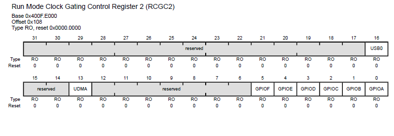
SYSCTL_RCGC2_R |= 0x00000020;
b) Initialize a counter variable to store the number of times a switch on PF4 has been pressed:
- Create a falling edges variable
volatile unsigned long FallingEdges = 0;outside of the initialisation function, and set it to 0 inside the initialisation function. FallingEdges = 0;
c) Setup PF4 as digital input for the switch:
- Clear the 4th bit in the GPIODIR register to make it an input

GPIO_PORTF_DIR_R &= ~0x10;- Clear the 4th bit in the GPIOAFSEL register to disable alternate functions

GPIO_PORTF_AFSEL_R &= ~0x10;- Set the 4th bit in the GPIODEN register to make the pin digital enabled

GPIO_PORTF_DEN_R |= 0x10;- Clear bits 16-19 (PMC4) in the GPIOPCTL register to disable peripheral control for PF4

GPIO_PORTF_PCTL_R &= ~0x000F0000;- Write a 0 in the GPIOAMSEL register to disabled analog mode function

GPIO_PORTF_AMSEL_R = 0;- Set the 4rth bit in the GPIOPUR register to enable a weak pull up resistor in the MCU

GPIO_PORTF_PUR_R |= 0x10;
d) Setup PF4 as edge-trigger:
- Clear the 4th bit in the GPIOIS register to have PF4 be edge-sensitive (edge trigger)

GPIO_PORTF_IS_R &= ~0x10;- Clear the 4th bit in the GPIOIBE register so we don't trigger on both the falling and rising edge; interrupt generation will be controlled by the IEV

GPIO_PORTF_IBE_R &= ~0x10;- Clear the 4th bit in the GPIOIEV register to trigger on the falling edge, similarly setting this bit to 1 will have the corresponding bit trigger on a rising edge

GPIO_PORTF_IEV_R &= ~0x10;
e) Clear Flag 4
- Write a 1 to the 4th bit in the GPIOICR register to clear the interrupt flag (acknowledge)

GPIO_PORTF_ICR_R = 0x10;
f) Arm interrupt on PF4:
- Set the 4th bit in the GPIOIM register to arm the interrupt. This will send the corresponding pins interupt to the interrupt controller (IEV).

GPIO_PORTF_IM_R |= 0x10;
g) Setup the interrupt priority to be 5 (any priority below 5 will interrupt this interrupt, anything above 5 will be postponed/pending)
- In the Interrupts table (pg 102) we notice that GPIO Port F is Interrupt Number 30. We will use this information to select the correct PRI(n) register to write to.
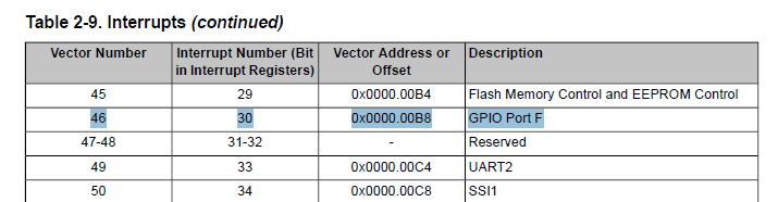
- The datasheet (pg 150) will tell us to use "Register 36: Interrupt 28-31 Priority (PRI7), offset 0x41C" so we will write to memory address 0xE000.E41C (defined as NVIC_PRI7_R) to manipulate Port F's priority level.
- To set Port F's priority to 5, we write "5" to INTC slot (INTA = 28 | INTB = 29 | INTC = 30 | INTD = 31) in Register 36.
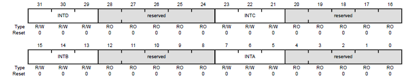
- 5 = [1][0][1][RO] = A (bit 20 is Read Only)
- A is used instead of 5 (0x00A0.0000) because the first bit in the 6th nibble of the long-word is RO(read only)
NVIC_PRI7_R = (NVIC_PRI7_R&0xFF00FFFF)|0x00A00000;
h) Enable interrupt 30 in NVIC
- In the Interrupts table (pg 102) we notice that GPIO Port F is Interrupt Number 30. We will use this information to select the correct EN(n) register to write to.
- Since our interrupt number for GPIO Port F is 30, we will write 1 to bit 30 in the EN0 register to enable interrupts for GPIO Port F

NVIC_EN0_R = 0x40000000;
i) Clear the I bit
- EnableInterrupts();
Interrupt Service Routine
void GPIOPortF_Handler(void){
  GPIO_PORTF_ICR_R = 0x10;      // acknowledge flag4
  FallingEdges = FallingEdges + 1;
}
- When in the ISR, we first want to acknowledge the trigger flag before doing anything else
- Write a 1 to the 4th bit in the GPIOICR register to clear the interrupt flag (acknowledge)
GPIO_PORTF_ICR_R = 0x10;- The next step is to increment the counter every time we enter the ISR
FallingEdges = FallingEdges + 1;
Main Function Routine
Reminder: Interrupts are called by a hardware event, rather than software call (ie: function();) so we do not need to define a function call in main() for any interrupts. An interrupt vector is setup in the initialization routine to enable an interrupt handler to work in the background. This is why you do not see the GPIOPortF_Handler() called in main()
int main(void){
  EdgeCounter_Init();           // initialize GPIO Port F interrupt
  while(1){
    WaitForInterrupt();
  }
}
EdgeCounter_Init();will run the port initialization and...- loop the
WaitForInterrupt();until an interrupt is invoked - WaitForInterrupt() places the processor in low-power mode while it waits for an interrupt