AeroShield - gergelytakacs/AutomationShield GitHub Wiki
Introduction
Application programming interface
C/C++ API
MATLAB API
Simulink API
Examples
Feedback control
Detailed hardware description
Circuit design
Parts
PCB
About
Authors
The AeroShield belongs to the family of control engineering education devices for Arduino that form a part of the AutomationShield project.
The AeroShield is based on an Arduino development board with a standard R3 pinout. The device itself is then built on top of a custom PCB with the rest of the electronic and mechanical components attached to it. The pendulum consists of a vertical and a horizontal carbon rod, connected with a 3D-printed elbow. The small coreless DC motor, commonly used for miniature drones, with a propeller, is mounted to the end of a pendulum through a 3D-printed motor connector. The rotating part of the pendulum is seated between two plastic bearings with a magnet attached to it in a 3D-printed holder. As the sensor, a Hall-effect rotational encoder is located behind the ball bearing in the axis of its rotational movement on a custom breakout PCB. The whole assembly is connected to the 3D-printed main body mounted on the PCB. The device represents a simple SISO system, where the goal is to control the angle of inclination of the pendulum by changing the lift created by the motor. The user may regulate motor thrust manually, using a potentiometer, or automatically by switching to pre-programmed trajectory.

The 3D printed parts — the main body, elbow, motor holder and magnet holder — are available for download as print-ready .stl files.
The application programming interface (API) serving the device is written in C/C++ and is integrated into the open-source AutomationShield Arduino library. This library includes header files for all available devices from the AutomationShield family. The AeroShield.h header file contains the forward declaration of the AeroClass for hardware interface methods. An AeroShield object is initialized from within this header. After including the header, the system can be simply started by calling the
AeroShield.begin();
method launching the I2C interface and starting the magnetic encoder itself. This method also provides information about the sensor's functionality by detecting the magnet and printing to the serial port whether the magnet can be sensed or not. After initializing the shield, the calibration procedure is called by
AeroShield.calibrate();
which reads the minimal and maximal angle of the pendulum and maps these values correspondingly to percentages (0-100%) or degrees (0-360°). After calibration, the minimal angle value is stored in the form of a global variable startAngle for later use.
The angular displacement of the pendulum is read by
y=AeroShield.sensorRead();
returning the raw angle reading, which is then mapped to an angle value in the range of 0-360°.
The current drawn by the motor is read by
y=AeroShield.readCurrent();
which provides an averaged current reading in the form of a floating point number.
By supplying the input u in the range of 0-100% to the
AeroShield.actuatorWrite(u);
method, the user can control the speed of the motor. This method also constrains the output value to avoid overflow and maps the input to an 8-bit PWM integer. The output of this method is then sent to the Arduino pin D5, which is used to deliver the PWM signal to the PCB circuitry.
Finally, a reference angle set by the user is acquired from the potentiometer by calling
r=AeroShield.referenceRead();
which returns the position of the potentiometer runner as a floating point scaled to 0-100%.
If you cannot program in C/C++ just yet, you may want to try out the MATLAB API for the AeroShield that enables to access the hardware through the MATLAB command line and scripts. It utilizes the MATLAB Support Package for Arduino Hardware which enables communication between the Arduino prototyping platform and the development computer.
To prevent confusion between the C/C++ and the MATLAB API, the two interfaces are as similar as possible. The MATLAB API is written in object-oriented script and the user must first create an instance from the class:
AeroShield=AeroShield;
The AeroShield device is then initialized by calling
AeroShield.begin('COM3','UNO');
which will simply load a server code to the microcontroller, unless it is not already present. This means that the closed-loop control by the API in MATLAB is not strictly real-time, since commands are transferred through the serial link between the board and the computer and may be affected by transfer speed or operating system behavior. However, being able to use the high-level MATLAB script allows you to run live experiments under this already familiar software platform and, most importantly, to create and test more advanced control frameworks with minimal effort.
The operation of the MATLAB API is otherwise completely identical to the Arduino version, mentioned before. Therefore, methods such as calibrate(), actuatorWrite() and referenceRead() are all implemented for the AeroShield in MATLAB library.
An even more intuitive tool for creating control loops and perform live experiments is the Simulink API for the AeroShield. It utilizes the Simulink Support Package for Arduino Hardware which supplies algorithmic units in blocks that access the core hardware functionality.
All necessary functions of the AeroShield are built into separate blocks available for use through the Simulink Library (see figure below) and may be combined with all the other available blocks to create feedback control applications.
The Simulink API custom library retains the naming convention and features for individual input and output blocks (Reference Read, Actuator Write and Angle Read) and a comprehensive block representing the entire device is also available ('AeroShield').

In direct contrast with the way MATLAB handles Arduinos, the block scheme in Simulink is transcribed into C/C++, then compiled to machine code and uploaded to the microcontroller unit (MCU). In other words, code is run directly on the microcontroller. Simulink not only transcribes the block schemes for hardware, it also maintains the connection between the development computer and MCU. This way controllers can be fine-tuned in a live session, or data may be displayed and logged conveniently.
The following sample examples were implemented in both Arduino IDE and Simulink API. The implementation in C/C++ uses the interrupt-driven sampling subsystem of the AutomationShield library. The same experiment can be conveniently launched from MATLAB and Simulink as well. The MATLAB API shall be used mainly for didactic and simulation purposes, but we do not recommend using it for research, since the computing of the control action is performed by the PC, hence the real-time execution of the instructions cannot be guaranteed. On the other hand, Simulink offers straightforward building of control loops using preprogrammed Simulink blocks. Using the Arduino IDE or Simulink API, the progress of the experiments can be followed in real-time through the Serial Plotter or a Scope block, respectively, or can be logged in MATLAB.
Let us start with PID control, since it most certainly forms an important part of any fundamental control course. The discrete PID controller assumed in this demonstration was hand-tuned. The figure below shows the result of its real-time implementation in Arduino IDE with the help of API, plotted in MATLAB. The aeropendulum tracks the desired angle reference, set manually using the potentiometer, swiftly and accurately. The example uses the PID framework from Automation-Shield to aid the learning progress of beginners even more.

Another example demonstrates the state-feedback control, in particular a linear-quadratic regulator (LQR). To design it, we used the state-space model obtained from the identification example, linearized around the angle of 45°. The controller was implemented using Simulink API, assuming calculation of angular velocity from position measurements via a finite difference method. The resulting control performance is beyond sufficient. As shown in figure below, the linear controller copes well with tracking reference output signal ranging from 20° to 75°, i.e. even far from the linearization point of the model itself.

AeroShield represents a single-input single-output (SISO) system, where the manipulated input is the voltage of the motor,
where
The worked example AeroShield_Ident_Greybox.m takes the experimental data and searches for the unknown parameters of the first-principle model based on both, nonlinear and linearized and state-space representation of the aforementioned ODE.
The input-output data for system identification were obtained by applying an amplitude-modulated pseudo-random binary sequence (APRBS) excitation signal. The unknown parameters are then found by a grey-box estimation procedure utilizing an appropriate search method implemented in MATLAB's System Identification Toolbox. The resulting models provide a very good match to the measured data as indicated in the figure below.

The AeroShield is an open hardware product, you are free to make your own device. If you come up with improvements, please let us know so we can improve our design as well. The discussion below should help you to improvise a similar setup for experimentation on a breadboard or perforation board. You may even order a professionally made PCB by a PCB fabrication service.
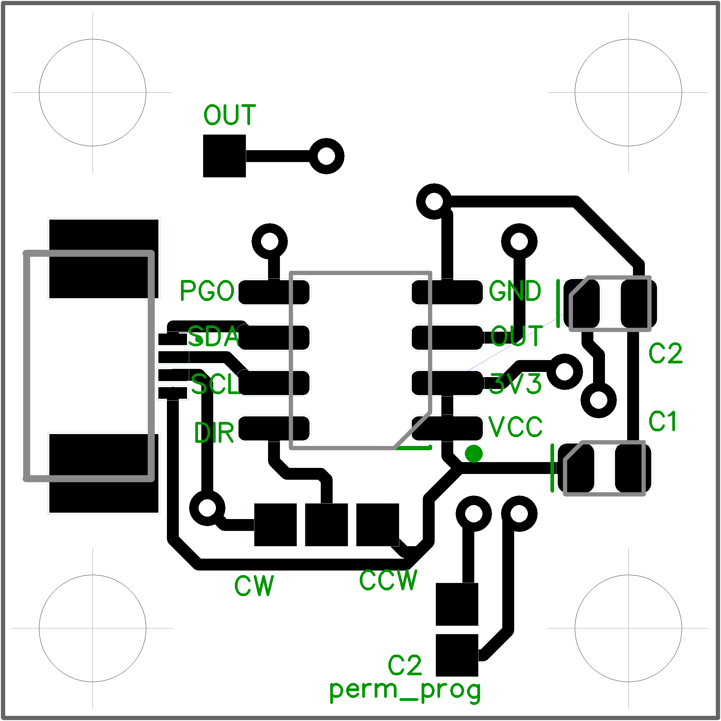
Following the electronic schematics, the voltage for the motor M1 is supplied from an external source through the barrel jack connector on the Arduino board, while the power supplied to motor is controlled by the low-side MOSFET transistor Q1 which receives a PWM signal from Arduino pin D5 through the \SI{1000}{\ohm} current limiting resistor. Floating states are handled by a 10kΩ pull-down resistor R9, while a diode D1 ensures back electromotive-force (EMF) protection. Operating voltage of the motor is 3.7V, hence a buck-down converter U1 steps down the voltage using resistors R1, R2 and R3, capacitors C1 and C2, and coil L1 layout. The microchip U2 is responsible for measurement of the current drawn by the motor, by comparing the voltage drop across the shunt resistor R4. There is also a 10kΩ pull-down resistor R5 on the output of the current monitor, and the VIN+ and V+ pins feature filter capacitors C3 and C4. The magnetic encoder is integrated into the breakout PCB with two capacitors, and connected to the I2C bus connectors of the Arduino (SDA, SCL). Finally, there is a potentiometer POT1 with a small plastic shaft that may be used to manually set the desired reference angle signal. The electronic schematics was designed in the free version of DIPTrace. You may download the circuit schematics of the AeroShield from here.

To make an AeroShield either on a PCB or on a breadboard you will need the following parts or their similar equivalents:
| part | name | Type/Value/Note | PCS |
|---|---|---|---|
| (b),(e) | PCB (shield + breakout) | FR4, 2 layer, 1.6mm thick | 2 |
| (k),M1 | Motor | High-speed DC coreless motor 7mm×15mm, 3.7V, 1mm shaft | 1 |
| (l) | Propeller | 4-blade propeller with ∅30mm | 1 |
| AS1 | Magnetic encoder | AS5600, 12-bit on-axis magnetic rotary position sensor | 1 |
| (d) | Disc magnet | ∅6mm, 2.5mm thick | 1 |
| (f) | Plastic ball bearings | IGUS BB-694-B180-30-ES | 2 |
| (g) | Carbon rod | 70mm long, circular cross-section ∅ 4mm ×∅ 3mm, 1m | 0.07 |
| (i) | Carbon rod | 100mm, square cross-section, 4mm × 3mm, 1m | 0.1 |
| (c),(d),(h),(j) | 3D printed parts | 3D printed, 49g of PETG filament, print time of 5:37h | 4 |
| U1 | Buck converter | TPS56339, 3A output synchronous buck converter | 1 |
| U2 | Current sensor | INA169, high-side, unipolar, current shunt monitor | 1 |
| POT1 | Potentiometer | 10kΩ ca14 | 1 |
| Turning knob | 5mm×18.7mm, e.g. ACP 14187-NE | 1 | |
| Q1 | MOSFET | PMW45EN2, 30V, N-channel trench MOSFET, SOT23 | 1 |
| R1 | Resistor | 30Ω, 5%, SMD, 0805 | 1 |
| R2 | Resistor | 40kΩ, 1% SMD, 0805 | 1 |
| R3,R5,R9 | Resistor | 10kΩ, 1% SMD, 0805 | 3 |
| R4 | Resistor | 100mΩ, 1%, shunt resistor, SMD, 0805 | 1 |
| R6,R7 | Resistor | 4.7kΩ, 5%, SMD, 0805 | 2 |
| R8 | Resistor | 100Ω, 5%, SMD, 0805 | 1 |
| C1,C2,C4,C1B | Capacitor | 0.1µF, SMD, 0805 | 4 |
| C3 | Capacitor | 22µF,50V, SMD, 0805 | 1 |
| C2B | Capacitor | 10µF, SMD, 0805 | 1 |
| D1 | Diode | 1N4001 DO-214, 50V, 1A | 1 |
| J1 | Connector (sensor) | FFC, 0.5mm, 4-pin | 2 |
| FFC cable (sensor) | 4-pin, min 15cm | 1 | |
| L1 | Inductor | 10µH, SPM6530T-100M-HZ | 1 |
| Connector (motor) | 2×1pin, 0.1" pitch | 1 | |
| Jumper cable (motor) | min. 35cm | 1 | |
| Header (motor) | 2×1pin, 0.1" pitch | 1 | |
| Screws | DIN 912, 4pcs. M3×40, 4pcs. M4×15 | 8 | |
| Nuts | DIN 934, M4 | 4 |
Note that the total cost of the above components and thus of the entire AeroShield is no more than $25 excluding labor, postage and soldering material.
The printed circuit board was also designed in the freeware version of the DIPTrace CAD software. The PCB is two-layer. The DIPTrace PCB layout and circuit schematics can be downloaded here, respectively, while the ready-to-manufacture Gerber files with the NC drilling instructions are available from here.
The assembled shield is fixed mechanically and electrically to the Arduino board through stackable header pins. The location of the components is also illustrated in the PCB layout below. The pendulum body is attached through 4 pre-drilled holes made in the manufacturing process.


This shield was designed and created as a bachelor's thesis at the Institute of Automation, Measurement and Applied Informatics. The Institute belongs to the Faculty of Mechanical Engineering (FME), Slovak University of Technology in Bratislava in 2021/2022.
- 3D-model design: Peter Tibenský
- Hardware design: Ján Boldocký, Erik Mikuláš, Denis Skokan, Peter Tibenský, Anna Vargová, Dávid Vereš, Tadeas Vojtko and Gergely Takács
- Software design: Peter Tibenský, Anna Vargová and Gergely Takács
- Wiki documentation: Peter Tibenský, Erik Mikuláš and Gergely Takács

Takács et al., 2018-2023. The hardware design, software and manual featured in this repository is licensed under a Attribution-NonCommercial-NoDerivatives 4.0 International (CC BY-NC-ND 4.0). Please consider citing our work in your publication.
