RACK Data Model - ge-high-assurance/RACK GitHub Wiki
Logical Layer Data Model
The logical layer of a data model describes data in terms of the domain, in the way that users would describe their data. RACK uses a specialization of a semantic data model called the entity-relationship (E-R) model as its conceptual model framework. In this type of data model, there are entities that often have relationships with other entities, and both the entities and relationships may have attributes.
RACK leverages two distinct sub-classes of logical model: provenance models and structural models.
Understanding the diagrams
The diagrams below give a visual representation of the data model using a graph representation. In addition to the diagrams below, interactive browsing of the ontology is available through the folder RACK-Ontology/Graphs and the starting point is Project.svg.
- Nodes in the graph represent classes of data that can be stored in the database.
- The attributes that can be associated with instances of those classes are listed on those nodes.
- Solid edges in the graph represent named relationships between instances of these classes.
- Dashed edges capture the sub-classing relationships between classes. When presenting the larger portions of the ontology the subclassing relationships are omitted to keep the graph understandable.
- Blue nodes are classes being defined in the current diagram
- Yellow nodes are classes that are already defined and are imported into the current graph. Notably any attributes or relationships specific to an imported node are not displayed.
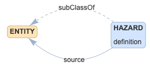
In this isolated example we can see that:
- HAZARD is a class of data that can be stored
- HAZARD is a subclass of ENTITY
- HAZARD has a source relationship to other ENTITY data
- HAZARD has a definition attribute
- HAZARD is being defined in this section
- ENTITY is already defined as is imported from an earlier section
Provenance Modeling in RACK
One part of the RACK data model deals with provenance: how and from where things documented in the RACK database came to be. This part of the RACK data model follows the W3C-PROV provenance model:
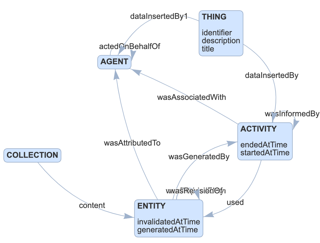
As shown in the figure above, the basic PROV model includes
- Entities, that are physical, digital, or other things. RACK can describe the provenance of these things, as well as associations between things.
- Activities, that explain how entities come into existence, or how the attributes of those entities change over time. Activities include actions by individuals or computer systems, as well as processes that combine multiple actions to achieve creation or alteration of entities. Activities not only create or alter entities: they may also use entities as inputs to control or affect that creation of alteration.
- Agents, that take roles in Activities or have responsibility for those Activities. An agent may be physical (a person, for example), digital (a piece of software), an organization, or anything else that may be held accountable for an Activity.
- Derivation, that describes how one entity's existence or characteristics are due to or derived in some measure from another entity. A specialized form of derivation is when one entity is a REVISION OF another entity.
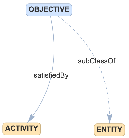
- Traceability, which is a variant of derivation that describes how an entity satisfies a need expressed by another entity. For example, a piece of software may SATISFY a requirement.
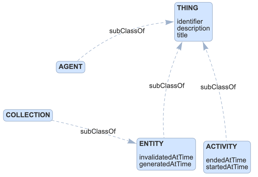
In this model all objects added to the system are described by a domain-specific unique identifier string called identifier -- effectively a primary key. All of the objects in the model will be instances of ENTITY, AGENT, ACTIVITY, or one of the sub-classes of these three core classes as described below. Note that some relationship classes in the ontology relate sub-class instances to class instances. This approach offers some generality (we hope not too much) in data modeling, that we hope will make it easier for TA1 users to ingest data successfully into RACK.
The full PROV model is more expressive than we currently need for ARCOS. However, as the program progresses, we may leverage other PROV expressions. We might for example use Roles that describe the function that an entity played in an Activity; and Plans that describe a process used to guide or control an Activity.
Structural Modeling in RACK
Another part of the RACK data model deals with structural relationships among entities. Systems for which ARCOS may build assurance cases are complex structures with many interoperable components. Unlike with provenance, we know of no de facto standard for describing the structures we see in the ARCOS domain. Instead, we fall back on intuitive compositional relationships such as isPartOf.
Physical Layer Data Model
The physical layer of a data model describes how data is represented. The aim of RACK is to prevent users from needing insight into our physical layer model, instead providing APIs that operate at the logical layer. At present, RACK aims to use the Resource Data Framework (RDF) triple store model, and may in future extend to a polystore model that mixes RDF with a graph database.
Details of the RACK Logical Data Model
The RACK data model is subdivided into modules. Interconnectivity within each module is intended to be rich, but interconnectivity between modules also exists. In the following sections, we describe each module's current definition.
In the diagrams below, elements shown in tan are base PROV classes, while elements in blue are our specializations for ARCOS. In our diagrams, and in some of our narrative descriptions of them, we use informal wording to describe our data model. While intended to be more intuitive than a formal meta-model description, it is also somewhat less precise. For example, we may say that a Requirement is an ENTITY, when in a formal description, we would instead say that each instance of the Requirement class is an instance of the ENTITY super-class.
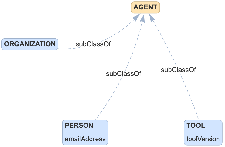
Agents
Analysis
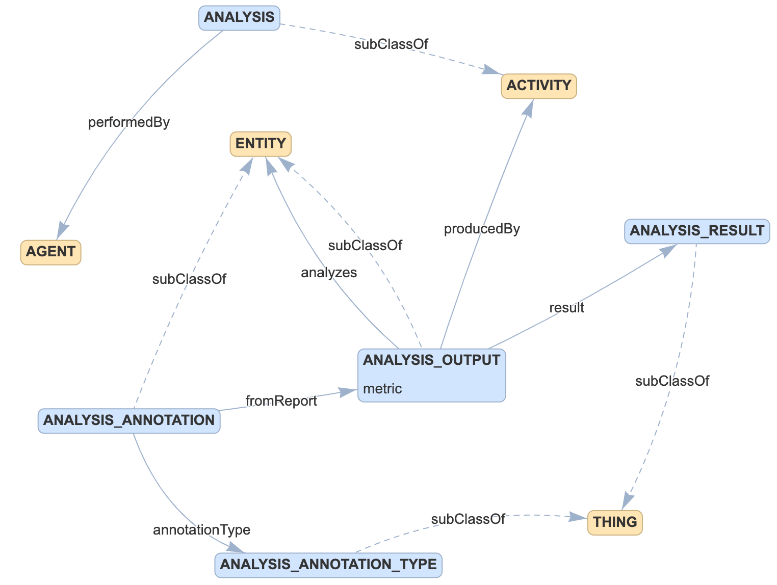
Analysis is a sub-class of ACTIVITY. Each instance of Analysis is performed by an instance of the AGENT class. Each Analysis instance produces an instance of Analysis Report. Analysis report is a sub-class of ENTITY. Each Analysis Report instance analyzes an instance of ENTITY, and has as a result an instance of analysis result.
TODO Add screen shot of ingest templates for this portion of the data model.
See the details here.
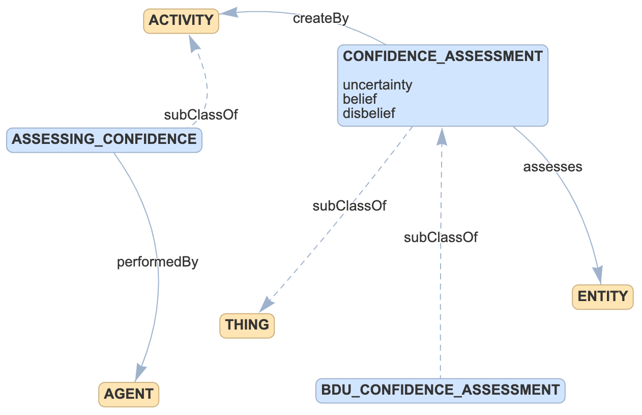
Confidence
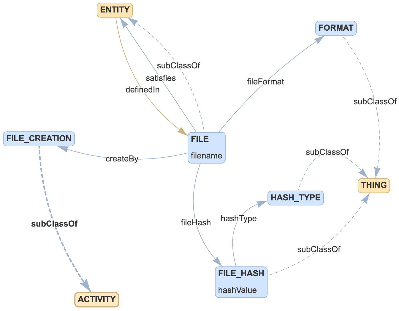
File
Hazards
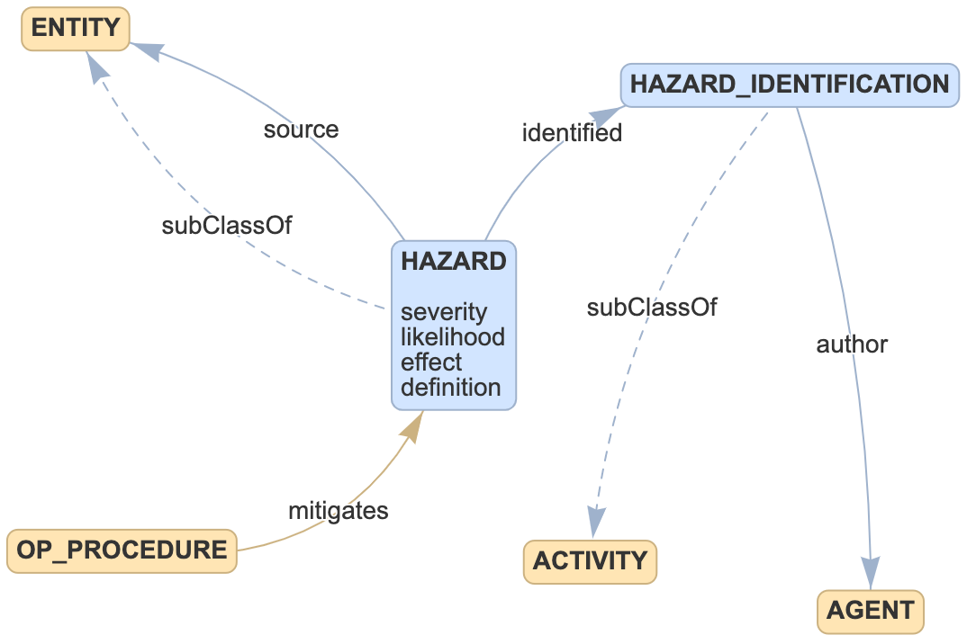
Hazard is a sub-class of ENTITY. A Hazard instance has as its source an instance of ENTITY. Hazard Identification is a sub-class of ACTIVITY. Each instance of Hazard Identification is authored by an instance of AGENT. Not shown yet in this model is the relationship class that connects the Hazard class to the Hazard Identification class.
TODO Add screen shot of ingest templates for this portion of the data model.
See the details here.
Requirements
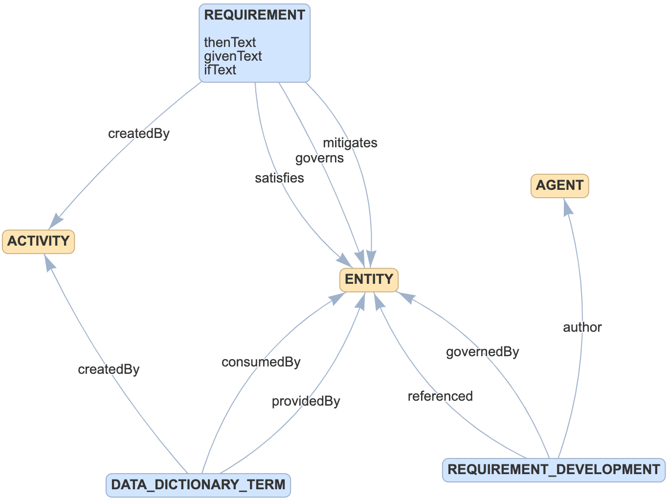
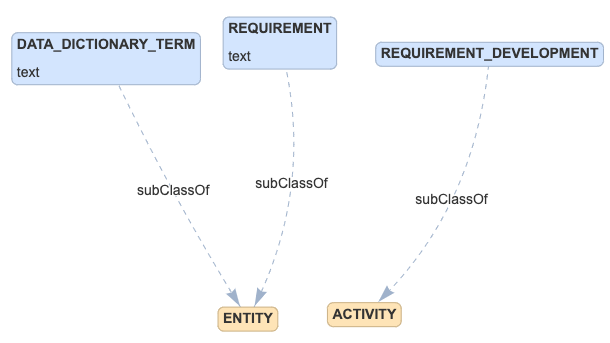
Requirement is a sub-class of ENTITY, and may represent a requirement at any level of abstraction. For example, a low-level requirements may be satisfied by a code files, while a higher-level requirement may be satisfied by lower-level requirements. A requirement instance has a human-readable representation of the requirement it models, stored in the text attribute.
The governs relation connects requirements to entities which are the subject of the requirement. These will typically be SYSTEM entities.
The satisfies relation connects requirements to higher-level requirements. These will typically be REQUIREMENT entities.
The mitigates relation connects requirements to the hazards being mitigated by the requirement. These will typically be HAZARD entities.
A DATA_DICTIONARY_TERM captures input and output elements of requirements. A human-readable representation of the term will be stored in the text property. These terms are linked to the requirements that use them as inputs with consumedBy and those that use them as outputs with providedBy. These terms help requirements to be linked at a finer granularity that a simple satisfies relation.
The createdBy relation connects requirements and data dictionary terms to the REQUIREMENT_DEVELOPMENT activity that generated them.
A REQUIREMENT_DEVELOPMENT activity tracks all of the data associated with creating one or more requirements.
The author relation connects a requirement development activity to the authors agents.
The referenced relation connects a requirement development activity to the source materials used in development. There currently isn't a detailed class for these materials so they would need to be represented as a generic ENTITY.
The governedBy relation connects a requirement development activity to the process documents guiding the development of these requirements. There currently isn't a detailed class for these materials so they would need to be represented as a generic ENTITY.
See the details here.
Reviews
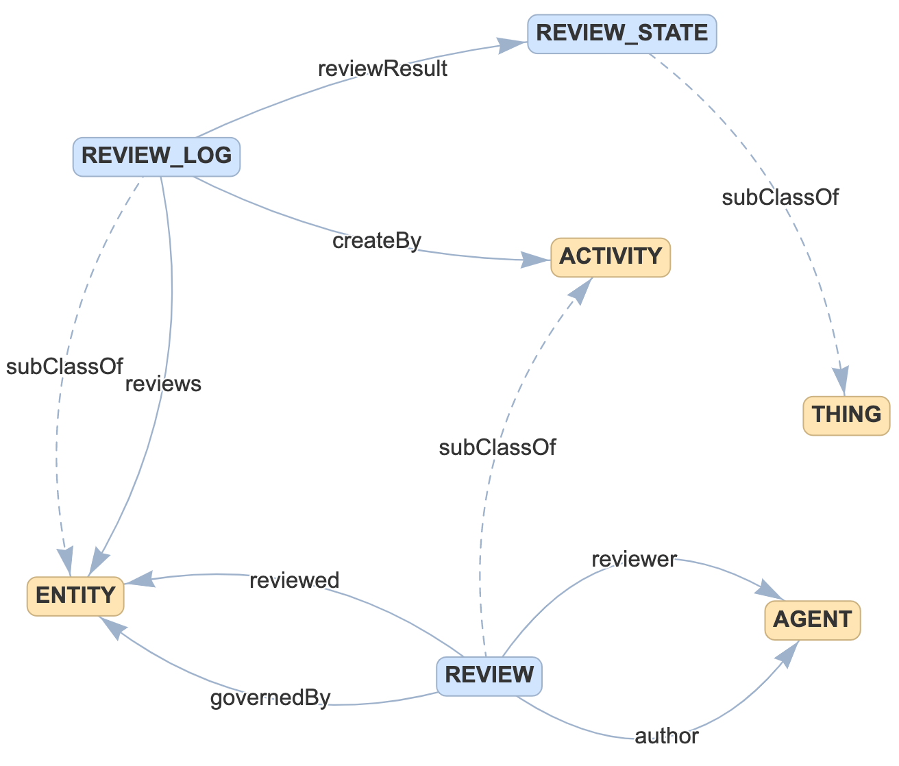
A Review is an ACTIVITY conducted by an Author and possibly Reviewers, governed by a review Process. The subject of the Review is the thing Reviewed.
A Review Log documents the Review of the thing Reviewed, and describes the Review Result, which is one of several possible outcomes. Each Review Log is created by a Review.
TODO Add screen shot of ingest templates for this portion of the data model.
See details here.
Assurance Arguments
An Argument Package is comprised of Argumentation Elements. This part of our ontology is still in development.
Structure of Software
This part of the ontology describes the structure of the software entities for which we store evidence. This structure information is meant as a framework off which we can hang that evidence, so we can easily find relevant evidence later, during assurance case construction.
Software comes in both executable and source flavors. These files are modeled using RACK's FILE class. The contents of these files can be described using the SWCOMPONENTS.
Software Entities
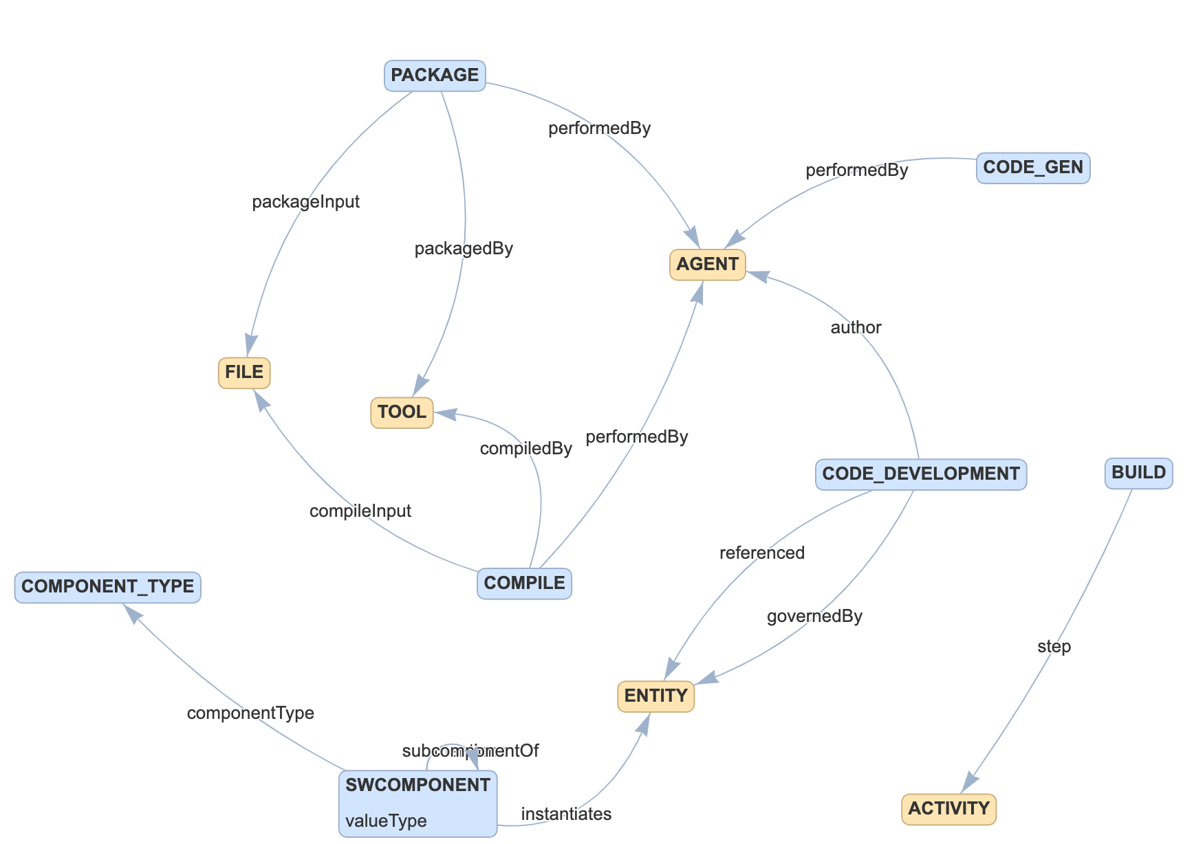
- SWCOMPONENT entities describe the contents of software FILEs whether executables or source files. These entities can be tagged with different component types to give information about the structure being defined. This set of tags typically contains things like global variables, source functions, class definitions, control-flow structures, modules, etc. The set of tags is extensible and intended to be extended to support the different kinds of software being modeled.
Software Activities
- COMPILE is the activity that uses CODE_FILEs in order to create OBJECT_FILEs. This will typically be associated with a COMPILER.
- CODE_DEVELOPMENT is the activity of generating CODE_FILES and other entities. It can be informed by processes, requirements, tests, or any other entity in the ontology. This activity will be associated with one or more developers.
- CODE_GEN is the activity of running a CODE_GEN to produce concrete CODE_FILEs.
- BUILD is the activity the can include connect many other software activities into a single high-level action. Many other activities are likely to be informed by a build activity. This could include the whole process of code-generation, compilation, linking executables, packaging, etc.
- PACKAGE is the activity that assembles any number of software executables, source files, configuration files, documentation into a distributable archive.
See details here.
System Structure
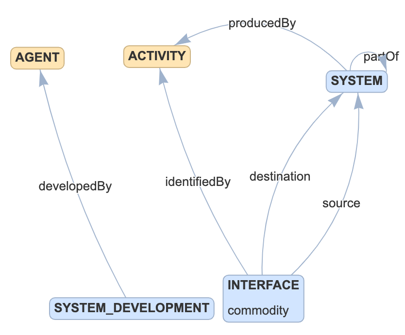
A System is a composable ENTITY that may be part of a larger ENTITY (also a System). Each System is produced by a System Development ACTIVITY. A System may require other entities to be present in order to work, and may provide entities as output. Each System has Interfaces, each of which has sources and destinations.
See details here.
Testing
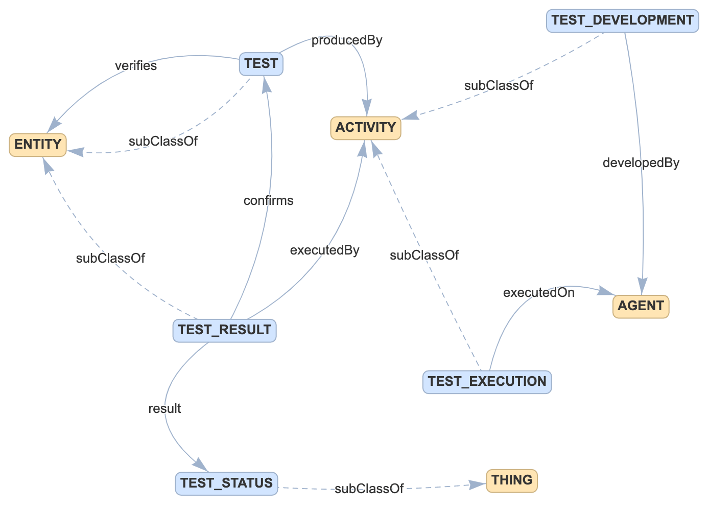
A Test is an ENTITY that Verifies another ENTITY (usually a Requirement). Tests are generated by Test Development ACTIVITIES that are conducted by AGENTs. Tests are Executed on ENTITIES (usually Systems) and generate Test Results that include a Status (Pass, Fail, Indeterminate) that Confirms an ENTITY (usually a Requirement).
TODO Add screen shot of ingest templates for this portion of the data model.
See details here.
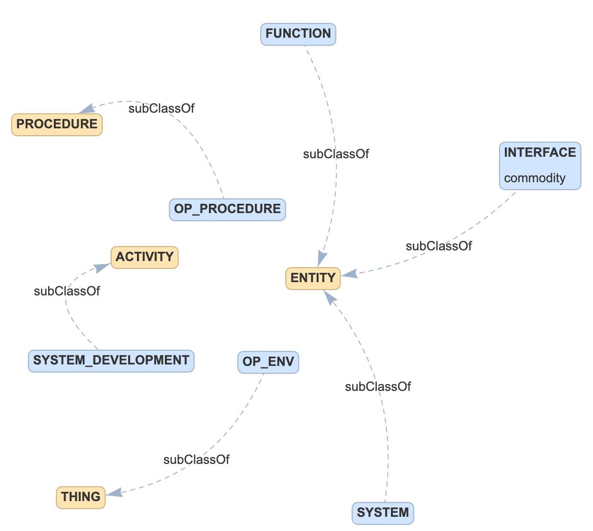
Documents
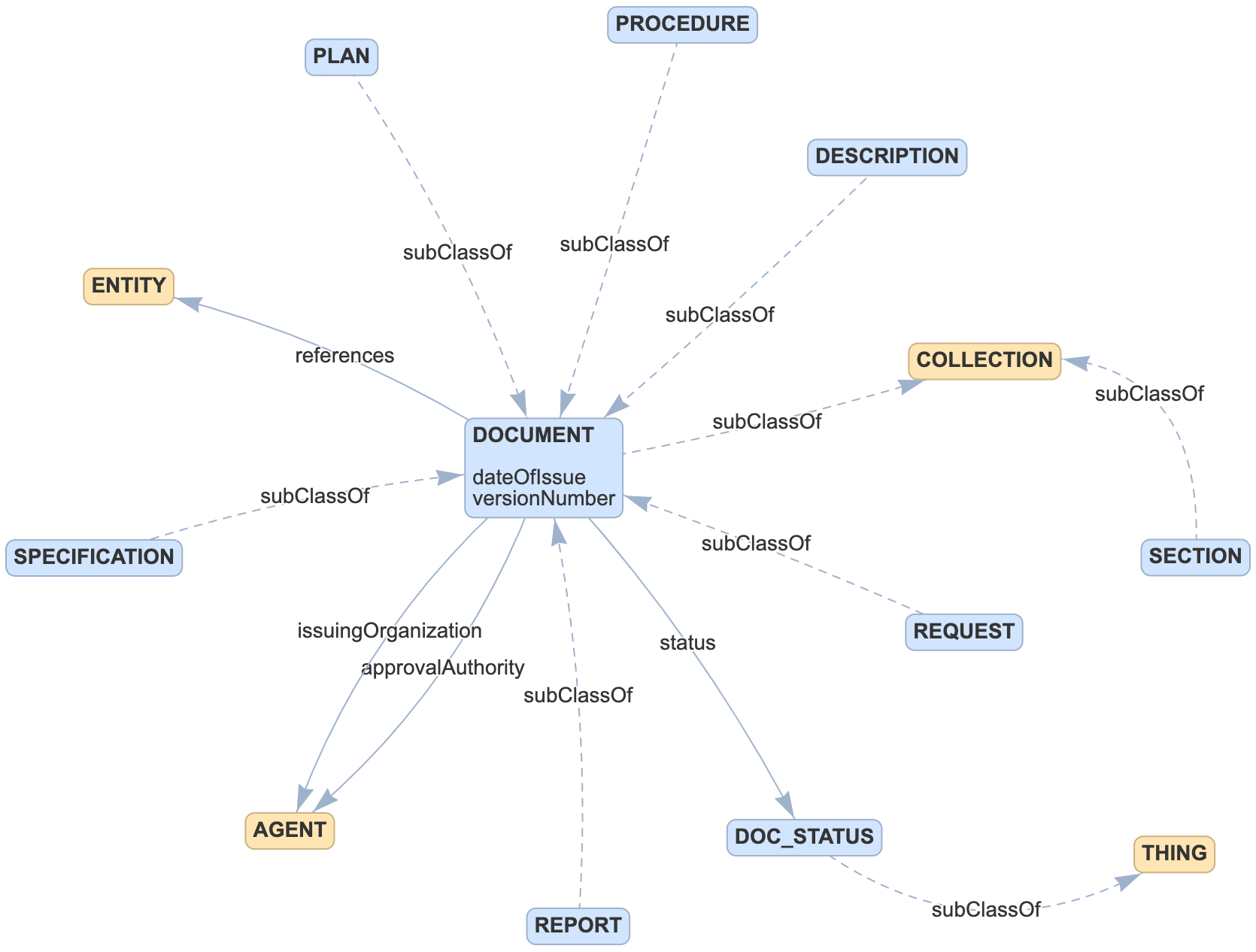
Documents are collections of ENTITYs originating from the same published artifact.
- DESCRIPTION an ENTITY that represents a planned or actual concept, function, design or object.
- PLAN an ENTITY that presents a systematic course of action for achieving a declared purpose, including when, how, and by whom specified activities are to be performed.
- PROCEDURE an ENTITY that presents an ordered series of steps to perform a process, activity, or task.
- REPORT an ENTITY that describes the results of activities such as investigations, observations, assessments, or test.
- REQUEST an ENTITY that initiates a defined course of action or changed to fulfill a need.
- SPECIFICATION an ENTITY that identifies, in a complete, precise, and verifiable manner, the requirements, design, behavior, or other expected characteristics of a system, service or process.
- SECTION an ENTITY that provides a generic grouping of ENTITYs with a source document.
Process
Process objectives describe the activities/services/strategies that will be delivered as part of implementing the program.
- OBJECTIVE an ENTITY that identifies tasks from a process for which evidence must be provided to show that the task has been completed.
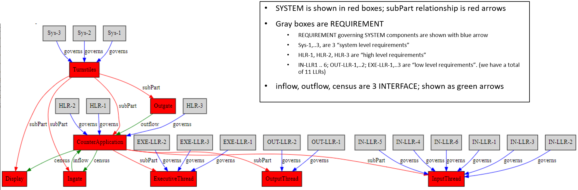
System Component Dependencies
The ontology structure defined and the data for the Turnstile model allows for incorporating system structure including interfaces / dependencies between system components. To illustrate this, here is a visualization that shows the Turnstile system structure on which the requirements and the interfaces between system components is also shown.
Properties
Notes
Notes have been added to properties to provide informative text. A comprehensive view of all the "notes" is available in the generated file PropInfo.csv.
Temporal Properties
The ontology has been expanded with temporal properties on entities and activities. These properties are optional. Entities now support a generatedAtTime and invalidatedAtTime. Activities now support startedAtTime and endedAtTime.
It is important to note that these temporal properties are not metadata. They record information about the world being modeled. These properties do not tell us when data was added or removed from the database itself.
It will depend on the particular data to understand what these properties mean and which of them will be used. If an object file is created by a compile activity it might be the case that only the object file has a generatedAtTime while the compile activity might have no temporal properties recorded.
Here are some examples:
- A file might have a
generatedAtTimeto track its creation. - A requirement might have an
invalidatedAtTimewhen a project's requirements were revised. - A requirement development activity might have a
startedAtTimeandendedAtTimespanning its lifetime.