Antenna Design - g7kse/CanSat GitHub Wiki
Our transceivers are going to need antennas, just like every other transceiver. The type of antenna is what is up for grabs. The RFM96W works on the 70cms band, that's 433Mhz. So to get the wavelength we need to do a bit of maths. The equation we need is:
v is velocity - which in this case is the speed of light or 299,792,458 m/s f is frequency - which in this case is 433MHz or 433,000,000Hz
so re-arranging for wavelength we get:
This gives us a wavelength of 69.24cm. We approximate this to the 70cm band, which is an amateur radio band in the UHF part of the spectrum.
Transmitter
What kind of antenna do we need. The most basic is a 1/4 wave vertical. Simply dividing the wavelength by 4 gives us a basic antenna of length 173mm. Simply attaching a 173mm length of wire will give us a basis antenna. This is probably all that is needed for the CanSat.
The 1/4 wave antenna is going to be are starting point for the transmitter. If we wanted to test the efficiency of the antenna we would need to get into the theory and practice of managing the Voltage Standing Wave Ratio and velocity factors. This is a bit of overkill for this exercise but is useful background knowledge to understand resonance and antenna systems.
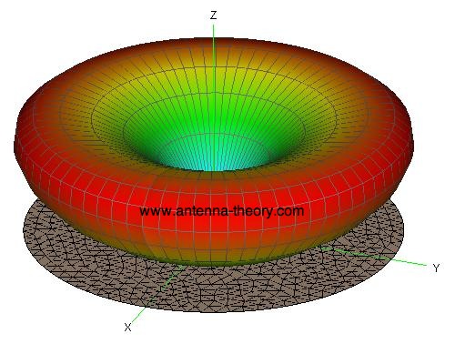
Before we leave this it is worth noting that this type of antenna is omnidirectional. It radiates equally in all directions perpendicular to the plane. The image below from Antenna Theory website gives us the idealised radiation pattern. Note that the orientation of the antenna, which is half of a half wave dipole i.e. a quarter wave is vertical. If the antenna is on its side then the pattern is rotated 90 degrees also.

Receiver
The receiver is going to be on the ground. The quarter wave antenna might just work.But we also might want to have a bit of directivity and some way of improving the signal, or gain. For this a common type of antenna is called a Yagi, or Yagi-Uda, after the inventor(s). This antenna type has the ability to have forward gain and to help reject signals from other directions. They are commonly seen on roof tops as TV antennas. The UHF TV bands in the UK are quite close to the 70cm band in fact, so sizes are quite similar. The antenna is made up of a reflector at the rear, a driven element and one or more directors. The greater the number of directors the greater the gain (with diminishing returns) and also the increase in directivity. So for high gain antennas, you need to point the quite accurately to get the best out of them.
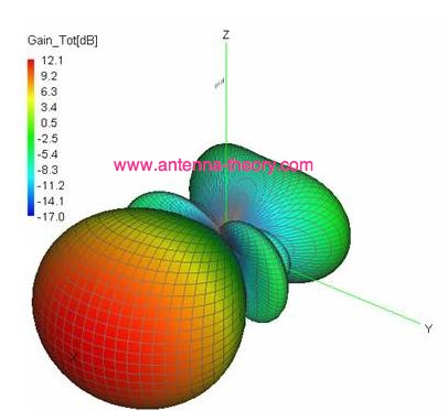
A similar plot from the Antenna Theory website for the Yagi design is as below

To calculate the antenna size we need the same information as before, namely the frequency at which we are going to operate i.e. 433MHz. So, to calculate the lengths of the reflector, driven and director elements we can use a Simple Online Caluclator to do the sums for us. Note that there are many tweaks to the original design which alter boom lengths, driven element configuration to include matching systems and so these are approximations. As his is a receive only antenna we can largely ignore some aspects but we will cover these anyway.
*** Matching and VSWR or SWR
To get the most out of and antenna and to reduce any likely damage to a transmitter the antenna system needs to be resonant. If the system is not resonant then there are implications.The general term for this is Impedenace matching. It gets complicated very quickly but the simple rule of thumb is that transceivers are generally designed around 50 Ohm impedance (over the air TV systems are an obvious exemption to this as they are 75 Ohms). Our connectors, cables & antenna like to be at 50 Ohms. Anything outside of that and we start to introduce losses which we note as VWSR or SWR (depending on how you like to see it).
- Our connectors (in the case of the RFM96W are SMA type) are 50 Ohms. One less thing to worry about.
- Our coaxial cable is 50 Ohms. But a feature of coaxial cable is that it is unbalanced. You get a bonus that it is easy to manage but a minus with the unbalanced nature. the length of cable can affect the impedance though.
- Our antenna is 50 Ohms and resonant by design and balanced - Uh Oh! The cable is unbalanced but the antenna is balanced
If we were to transmit directly into the unbalance system we would typically see some of the energy return back down the coaxial cable and result in RF not being where we need it. In poor systems that results in energy that can affect surrounding environment as noise, in really poor systems it can do strange things like turn off the TV or affect computer systems when powers are higher than what we are dealing with.
To get the most out of a system there needs to be a matching network. There are many ways of doing this, however for a receive only antenna we can probably ignore this. If performance is not what you were expecting then consider adjusting the antenna design to include a matching network.