Throttle - frk2/opencaret GitHub Wiki
Overview
Above all the three modules of Drive By Wire system, Throttle is the easiest way to implement. We suggest you to implement the throttle first before you'll move on to the next step (steering, brake, shift, blinkers, horn, etc).
Sensor Interface Module
The ETC system can be controlled by removing the accelerator position sensor (APS) input to the ETC microprocessor and injecting spoofed position values. The pedal position sensor uses redundant position sensors that both output analog signals. The full range of sensor position values correlate to the full range of throttle from "closed throttle" to "wide open throttle." By injecting the two spoofed position sensor values the throttle can be controlled.
The Kia ECU implements fault detection on the accelerator pedal position sensor by detecting discontinuities in the analog signals coming from the sensors. If any discontinuities appear the car will go into a fault state, with the symptom of having the mapping of the accelerator pedal greatly reduced. To overcome this the new throttle microprocessor will interpolate between the sensor position values and the spoofed values before sensing spoofed positions.
A relay is used to switch the input of the ETC microprocessor from the stock pedal position sensor and the spoofed positions.

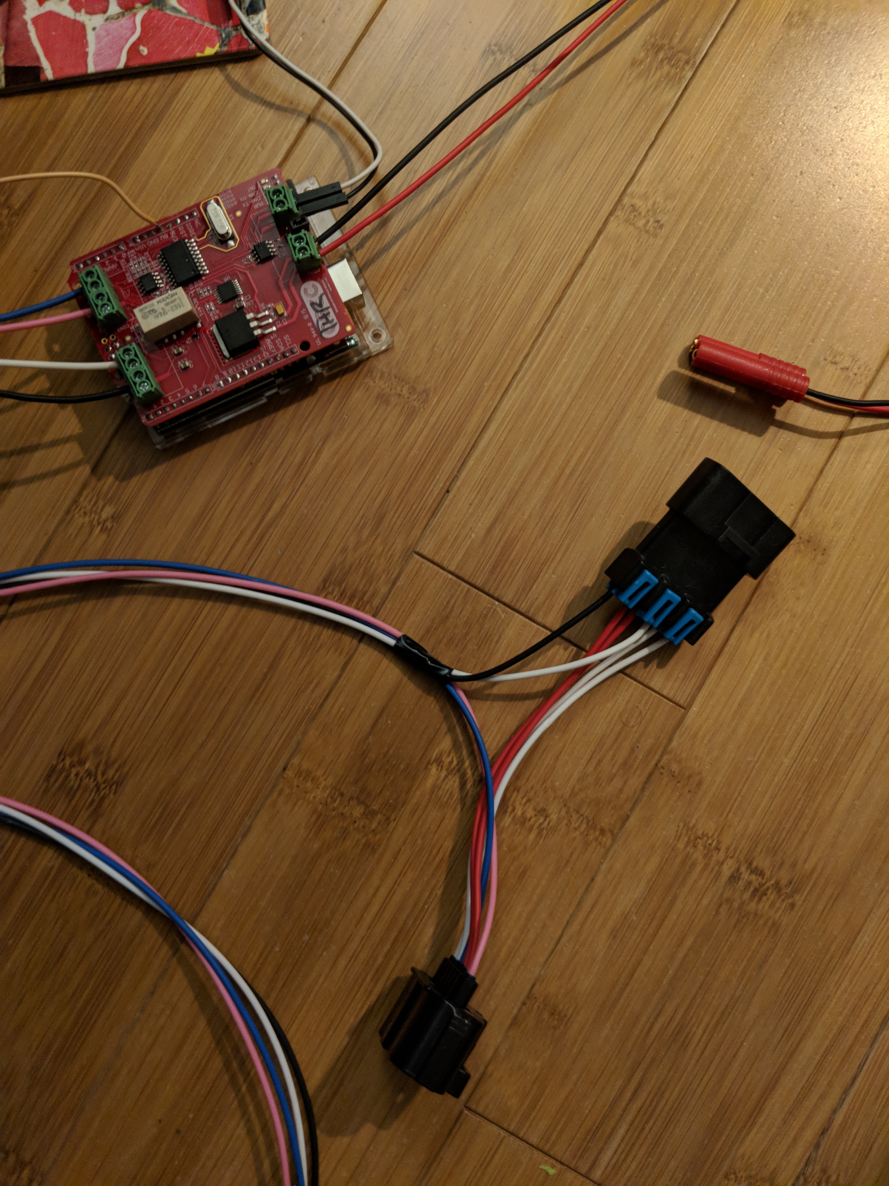
Cable harness
- APS Receptacle
- APS Plug
- 18G AWG Automotive wiring
Original APS Schematic on the Soul EV

As you can see that the APS1 and APS2 are connected to the EPCU straight to the Accel pedal position. The Accel Pedal position is already drive-by-wire from stock so it sends a voltage throttle command without any mods. We will try to spoof this signal with the throttle module.
- Layout of APS Pinout can be followed below:

Installing the throttle
- Step 1 Locate the Accel Pedal Position Sensor

- Step 2 Disconnect the Pedal Position Sensor and Connect the Throttle cabling
Follow the diagram below for the connection

Keep in mind the APS2 is SIG HIGH and APS1 is SIG LO. The throttle harness should not follow and match the color coding scheme on the throttle diagram. The pinouts stay the same as follow.

- Step 3
Connect the power unit with the emergency stop power bus.
- Step 4
Wire the module to the Gateway Module Control CAN bus.
Bench testing
The accelerator pedal is very easy to simply remove from the car. We would recommend you do this since its super simple to bench test this one pedal and get used to how things are.
The APS needs a 5V source to operate. We can use external 5V DC power supply rated at 300 mA to power the APS for testing. Other method is using the Arduino 5V from the shield. Both pin 4 and 5 from EPCU APS need 5V to power APS1 and APS2 (Please refer to the Kia schematic).
Attach throttle board to your favorite Can to USB convertor. You should immediately start seeing Throttle reports. See Can Control