Shchematic Circuit Diagram - freeDSP/freeDSP-OCTAVIA GitHub Wiki
FreeDSP OCTAVIA version 0.1 Schematic PDF(2 Layers PCB)
FreeDSP OCTAVIA version 0.2 Schematic PDF(2 Layers PCB)
FreeDSP OCTAVIA version 0.25 Schematic PDF(2 Layers PCB)
FreeDSP OCTAVIA version 0.30 Schematic PDF(4 Layers PCB version)
FreeDSP OCTAVIA version 0.31 Schematic PDF(4 Layers PCB version)
FreeDSP OCTAVIA version 0.33J Schematic PDF (4 Layers PCB version)
FreeDSP OCTAVIA version 1.00 Schematic PDF (Final Release)
FreeDSP OCTAVIA version 1.1 Schematic PDF (Fixed ACM9070 Footprint design)
FreeDSP OCTAVIA version 1.2 Schematic PDF (Simplified bypassing differential driver. YORK ready design)

The Embedded power rails are as follows...
- U5 for Raspberry-pi +5V SMPS
- IC1 for Digital block +3.3V SMPS
- U3 as an Analog +5V series regulator
- U7 as an Analog +3.3V series regulator
- U8 SMPS for -5V negative power supply

This Board uses only a single-power voltage from DC 6.5V to 9V wall Adapter supply. (2.1mm Center Pin Positive, minimum capacity required 2A for 9V, 3A for 6.5V-7.5V Using with Raspberry-Pi mk3 B+) A power line choke FL1 has been provided to reduce the common mode noise effects. Q7 has provided reverse voltage protection. The power ON/OFF anti-pop mute driver circuit was controlled with the mains power switch SW2. The "MUTE" line drives a solid-state audio output muting circuits. SW3 is the dedicated power switch for the Raspberry-Pi. U6 generates a timing of power-on-delay and shutdown-delay. this circuit controls U5 Raspberry-Pi +5V SMPS block.
Up to version 0.30, the series regulator chip AZ1117 compatible AMS1117 was used for U3/U7.

Indicates the power status of Raspberry-Pi and the Audio Muting functions.

An RGB LED is provided. Using the Vf for switching the colors.

A debug header J4 for the serial console is provided. Use the TTL-232R-3V3 an FTDI USB-UART Cable for this purpose. GPIO17 or GPIO26 can detect the power switch SW3 and shutdown/restart button SW1 status. You need to implement a shutdown sequence when the ideal port is tied down to low.
A delay shutdown feature is provided. If you install a demon process of watching GPIO17 (or GPIO26) automatic shutdown feature will be available. After you shutdown the Raspberry-pi, you can restart it by pushing the SW1 pushbutton.
This slot is I2S Input provided for USB-Audio Source.

If the Combo384 output MUTE during you select the USB, PCM5102A's XSMT (Soft Mute) will invoke. Also the protection for the DSD stream. This mute function also will be active during Power-On and Off.
You will find various Amanero-compatible USB-Audio Interface boards at Ali-Express. Such as follows...
| Board Type | Picture |
|---|---|
| Amanero Combo384 (Original) |  |
| xMOS Only |  |
| xMOS + CPLD |  |
| BRAVO Chip (A) |  |
| BRAVO Chip (B) |  |
If the DSD stream comes, the mute function should be activated.

A DSP-Reset button SW7 is provided. This action also applied to the DAC soft MUTE (i.e. XSMT).
This board uses I2C (address==0x70) for USBi and Raspberry-Pi access.

SOIC or DIP8 package SPI EEPROM is available for DSP's self-boot configuration. SW4 is an option for a selectable A/B boot feature(you need to remove R43 before populating SW4). During you connect the USBi, Raspberry-Pi's I2C bus will be disconnected automatically.
Switchless Optical and Coaxial S/PDIF Inputs are provided.

Each Input Bi-phase-mark signal is XOR processed, so you can not use them simultaneously. Please use only one Input.
A 512fs TCXO for 48kHz is provided. This enables to design capability of the External 96kHz Sampling ADC board.

The fan-out capability of DSP is limited. So the U15 drives the onboard ADC/DACs and the optional external ADC board.
A PCM1808 ADC is provided for the FM-Tuner or Tape-Deck such as legacy input sources.

This chip can run better SNR performance in 48kHz sampling frequency than 96kHz.

Header J3 is provided for the connection of the High-Quality extra ADC board. This was intended to add a feature of the Phono Input Board. You can use the following power rails...
- +3.3V
- +5V
- -5V

AUX0 through AUX4 will be useful for Analog-like control such as follows...
- AUX0 for Master-Volume
- AUX1-AUX4 for Gain-Trim or Change of Parameter Control.
Header J1 is provided. If you want to use external Pots, remove the onboard pots and connect them to the external pots.
An AUX5-ADC was used for this purpose.

Tapped Voltage divider and the rotary switch will make a digital look and feel, but the actual source selection should have been done with ADC value stabilization and applied the "look-up-table" processing for driving the MUX prepared for the Audio source selection. There are four levels of this control voltage plus you can tie it down to GND when the USB_MUTE == ON(High). The source Indicator LEDs header J13 is provided.
Two LED indicators are provided

MP6 and MP7 can control these LEDs. This was intended to use of Input Singal Indicator or Near Clipping Indicator.
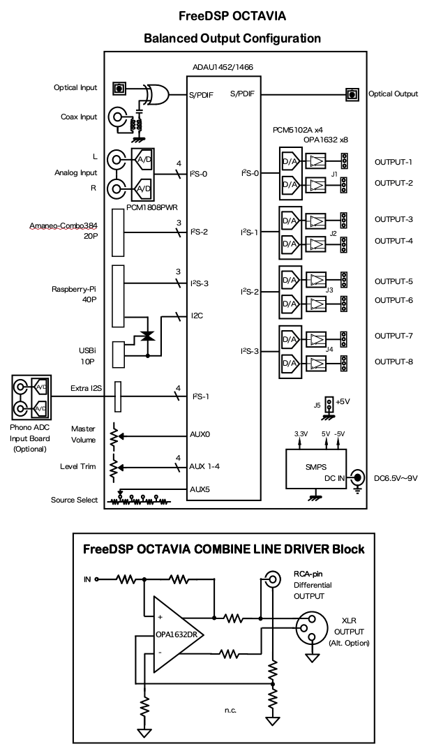
TI's PCM5102A/PCM5101A/PCM5100A are available for the D/A conversion of Output Audio Sounds. You can select various output circuit configurations.
This Line driver circuit can be configured as RCA-pin differential output, XLR-Balanced output.

High-quality full-balance line driver OPA1632R is used for each Differential RCA output or Balanced header output. Of course, you can bypass OPA1632R chip for the simple unbalanced output configuration. Each output has a power-on and Power-off muting circuit to eliminate pops during the main power transition.