Theremin shield design - fpga-theremin/theremin GitHub Wiki
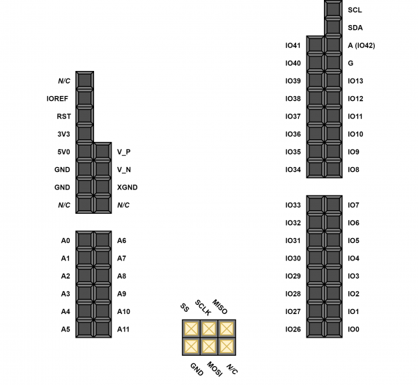
Cora Z7 available pins
2 PMod connectors - used directly to connect audio PMods
Arduino/Chipkit shield connector:
Requirements for shield
- Connects to CoraZ7 or compatible board via Arduino/chipkit shield connector
- Compatible with other Diligent FPGA boards with Arduino/chipkit connector
- Two Theremin Oscillator connectors (Vcc, GND, OSCout)
- LCD Screen + Touch connector - for Waveshare display
- Connector with 4 analog in (ADC) inputs for front panel pots (half-pmod form factor)
- Connector with 8 analog in (ADC) inputs for rear panel (e.g. for pedals/buttons) - PMod compatible
- Connector with 8 digital i/o lines in PMod form factor and 10K Ohm pull-ups, e.g. to support 2 encoders, 1 button, 1 LED.
Oscillator connectors
Oscillator connectors are 3-wire
Pin       Name        Description
------    -------     ----------------
1         Vcc         +3.3V
2         OSC_out     Oscillator signal output 3.3V logic level
3         GND         Ground
Connecting oscillators to Cora Z7:
Signal               Cora Z7 pin
---------------      -----------
Volume OSC_out
Pitch OSC_out
LCD connector
Waveshare LCD uses 40-pin connector.
24bit RGB is overkill, and there are not enough free pins on Arduino/chipkit connector. Let's use RGB 4-4-4 (12 bits) instead of RGB 8-8-8 (24 bits). Lower half of color component may be populated with the same value as higher half.
LCD header pin     Cora Z7 pin  I/O(Cora) Name      Description
--------------     -----------  --------  --------- --------------------------------------------
1                               I         IRQ       Touch screen interrupt (0 when pressed)
2                               O         5V        Power supply +5V
3                                         MOSI      Touch screen SPI data input - to MOSI of SPI
4                                         MISO      Touch screen SPI data output - to MISO of SPI
5                               O         SCK       Touch screen SPI clock - to SCK of SPI
6                               O         SSEL      Touch screen SPI select - 0 to select
7                               O         PWM       Backlight brightness control
8                               O         GND       Ground
9                               I         BUSY      Touch screen busy output
10                                        N/C
11                                        R0        Red bit 0 (connected to R4)
12                                        R1        Red bit 1 (connected to R5)
13                                        R2        Red bit 2 (connected to R6)
14                                        R3        Red bit 3 (connected to R7)
15                              O         R4        Red bit 4
16                              O         R5        Red bit 5
17                              O         R6        Red bit 6
18                              O         R7        Red bit 7
19                                        G0        Green bit 0 (connected to G4)
20                                        G1        Green bit 1 (connected to G5)
21                                        G2        Green bit 2 (connected to G6)
22                                        G3        Green bit 3 (connected to G7)
23                              O         G4        Green bit 4
24                              O         G5        Green bit 5
25                              O         G6        Green bit 6
26                              O         G7        Green bit 7
27                                        B0        Blue bit 0 (connected to B4)
28                                        B1        Blue bit 1 (connected to B5)
29                                        B2        Blue bit 2 (connected to B6)
30                                        B3        Blue bit 3 (connected to B7)
31                              O         B4        Blue bit 4
32                              O         B5        Blue bit 5
33                              O         B6        Blue bit 6
34                              O         B7        Blue bit 7
35                              O         DCLK      LCD data clock
36                                        N/C
37                              O         HSYNC     LCD HSYNC
38                              O         VSYNC     LCD VSYNC
39                              O         DE        DE=0 - sync, DE=1 - data
40                              O         GND       Ground
PCB
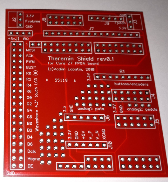
This design is shared on DirtyPCBs site.
NOTE: Core Z7 unsoldered connector routed on this PCB is actually useless since it shares pins from Arduino/ChipKit connector. It will be removed in next revision of PCB.