Oscillator design - fpga-theremin/theremin GitHub Wiki
Choosing type of sensor
Thereminists control pitch by moving right hand and volume by moving of left hand.
Digital theremin must have some type of sensor to feel hand movements
- Antenna capacity based sensors - like in classic theremins
- Optical sensors (luminance or laser distance meter)
- Ultrasonic distance sensors - I've tried to use it in Arduino based design - too low sensitivity
- Camera based sensor - high resolution high speed camera and complex video processing is required to get acceptable sensitivity and low latency
- More?
Capacitive sensor
Based on measuring of antenna capacity which is being changed when hand is moved near antenna.
Antenna capacity varies by ~10-15% for hand moves between far and near positions.
Capacity of antenna may be measured using RC or LC circuit.
RC type has too low sensitivity on far hand distances, and parameters too much depend on temperature. Useful for toys only.
LC tank based measuring provides much better stability and sensitivity.
For better results, LC tank should have high Q. C is the smaller the better. L (inductor) - air core is preferred.
LC resonant frequency measure
Following methods may be used for measuring of LC resonant frequency:
- LC oscillator - LC resonant frequency is output frequency of oscillator - classic way
- Pass fixed reference frequency to LC input, detect phase shift between signals before and after LC - phase shift 90 degrees will be when reference frequency equals to LC frequency. XOR logic may produce PWM signal depending of phase shift.
- Use PLL to control input frequency for LC, track phase shift by PLL to keep frequency equal to LC resonance (dewster's method).
LC oscillator
LC oscillator is classic way to measure antenna capacity.
It has good sensitivity on far hand distances from antenna.
The only problem here is that it's hard to measure frequency of oscillator with high precision.
LC oscillator frequency varies in range 3-4% (or less, depending on oscillator type) reacting on hand movement.
Direct measuring of this frequency is usually hard, at least for MCUs.
Usually some heterodyning technique is used to extend frequency change rate, or even to convert it to output pitch range - this method is used in most of analog theremins and some digital theremins.
Direct measure of LC oscillator frequency using FPGA is possible. Using hardware deserialisation components and delay lines for oversampling may allow to get more bits of measured frequency value.
Averaging of measured values allows to increase effective number of bits.
Averaging adds better precision but adds latency. Latency (time between hand movement and sound changing) must be as low as possible. Latencies more than 10 ms are easy to feel. The bigger latency is, the harder is to play proper note (e.g. move hand based on audio out to keep desired pitch).
I believe, for good digital theremin, latency should be less than 1ms.
Bad example of digital theremin with high latency is Moog Theremini (it's latency is up to 0.2 seconds).
With FPGA it's possible to create design with latency of a few samples (e.g, 0.05ms or 0.1ms).
Schematic
Schematic is based on design proposed by TW forum user dewster.
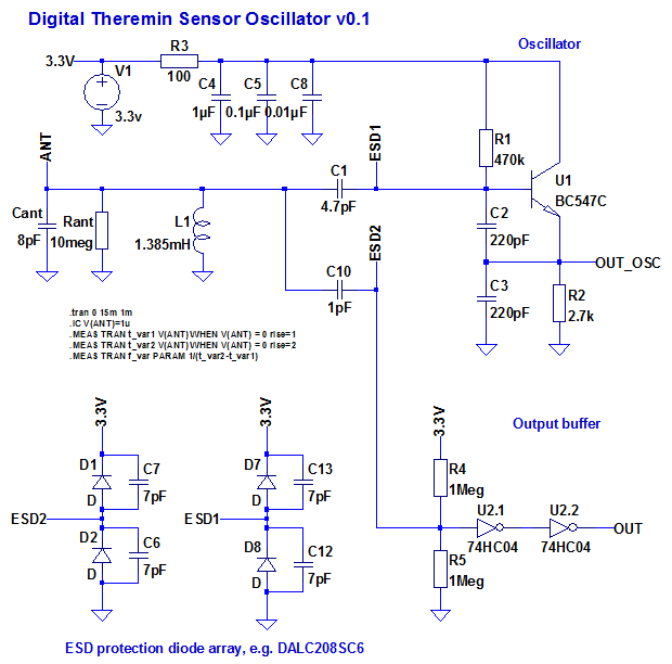
Simulation in LTSpice helps a lot to play with schematics and part nominals to get better result.
Simulation screenshot (red - voltage on antenna, green - on emitter, blue - digital output):
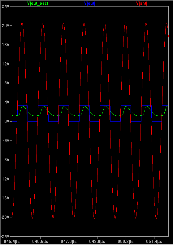
LTSpice model is shared here on git
Inductor
Inductor is important part of theremin design.
It should have high Q.
It's better just make air core DIY inductor.
Choosing some stuff for frame and mounting.
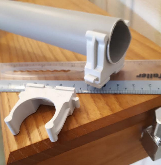
Take 25mm plastic pipe with mounting clips, cut 6cm long piece, wind 0.1mm coil-to-coil.
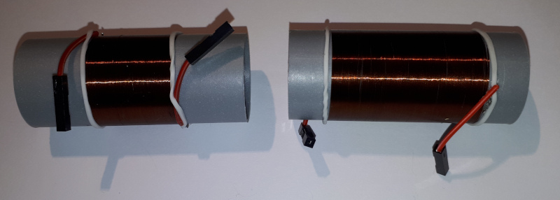
Volume and pitch oscillators must have different frequencies.
Usually volume oscillator frequency is selected to be lower - winding length twice longer than for pitch oscillator helps.
Interface connector
3-wire interface is enough:
- Vcc 3.3V
- GND
- OSC out signal (3.3V CMOS logic level square, duty cycle ~50%)
PCB
Creating schematics and simulating in LTSpice.
Routing PCB in DipTrace freeware version.
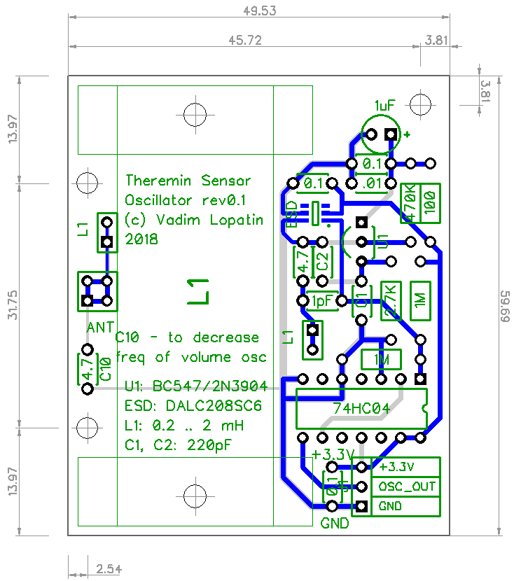
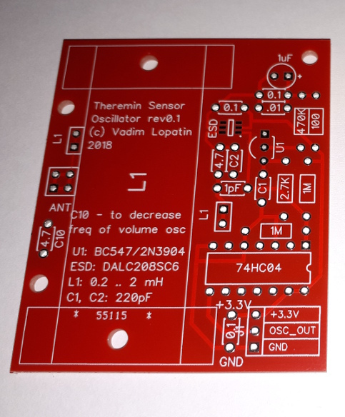
Photo of PCB manufactured by DirtyPCBs:
PCB in DipTrace format, as well as gerber files are share here on git
This design is shared on DirtyPCBs site as well.
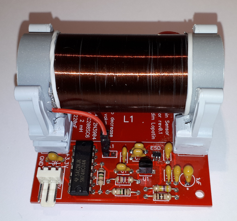
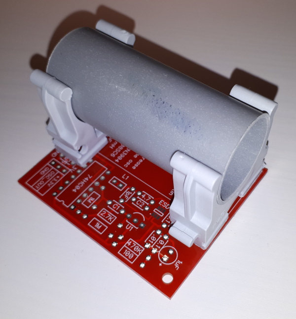
Soldered PCB:
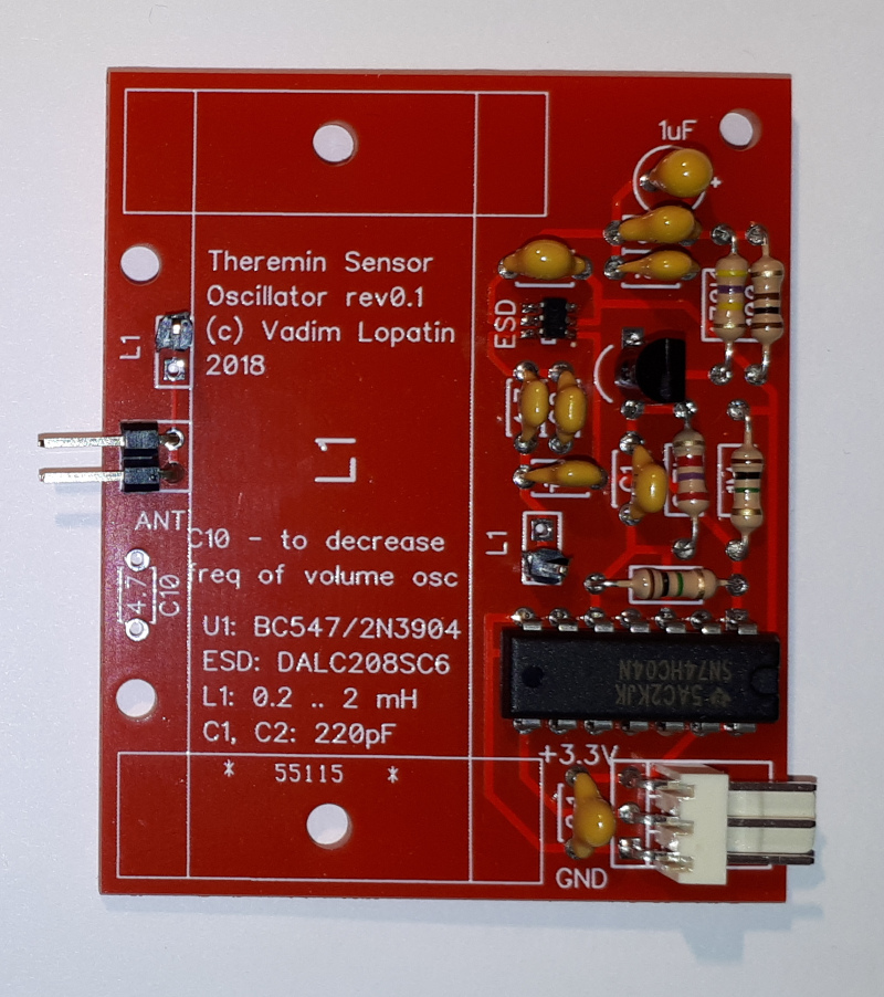
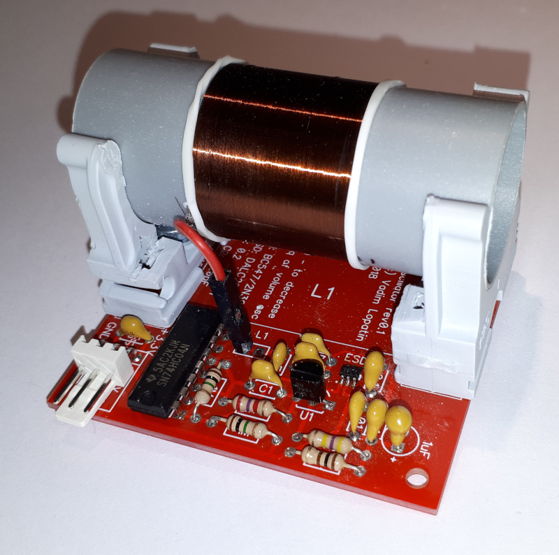
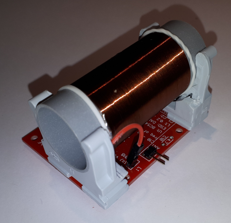
Oscillator PCBs with mounted coils: