Cabinet design - fpga-theremin/theremin GitHub Wiki
This article describes classic theremin cabinet design suitable for most of analog and digital theremin projects.
Easy to reproduce - plywood laser cut based, "plumbing" antenna mounts.
Form factor
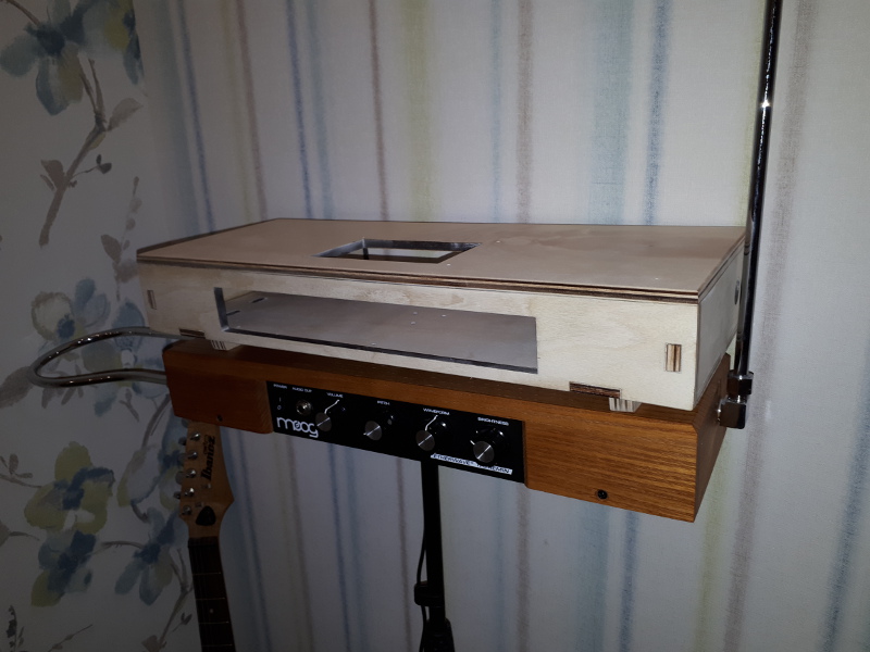
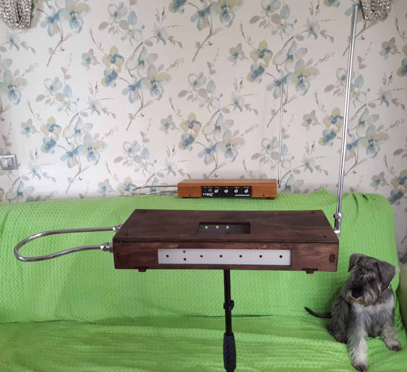
I like Moog Etherwave Theremin (EM Theremin) form-factor.
- It's familiar for every thereminist.
- Space inside cabinet is enough for fitting almost any hardware.
- Mic stand mount is must have.
- DIY wooden cabinet is easy to build and inexpensive
Antennas
"Plumbing" style antennas solution like in etherwave (with gas/water fittings, and copper tubes) is easy to build.
Cover
- LCD touch screen
- Optional speaker(s) may be useful sometimes
If you don't need LCD, edit InkScape design file.
Front panel controls / sockets
- It makes sense to place headphone connector with volume pot on front panel
- 1-2 encoders and 2-3 pots would be enough for implementing rich set of controls
- Some button(s) and/or LEDs - not sure if they are helpful if there is LCD touch screen
Rear panel controls / sockets
- Audio Line Out - for connecting amplifier (doesn't it make sense to add to mono, mono + stereo, or stereo only outputs?)
- Audio Line In - stereo input, e.g. for aux accompaniment input
- Power input socket
- Power switch
- USB input for FPGA board programming can help to avoid removing cover when programming
- Optional USB OTG may be used to interface with PC - e.g. as USB MIDI or USB HID device
- Ethernet - not sure if it could be useful
- Several sockets to connect foot buttons and/or pedals - e.g. may be used to control some effects and loop feature
Plywood laser cut technology
- Plywood looks as cheap but good solution.
- Making laser cut design simplifies building of cabinet. Less work, better result.
- Glue + a few screws - easy to assemble.
Laser cut design file for 8mm birch plywood:
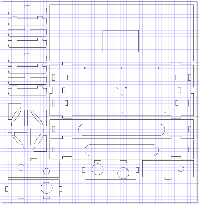
If you don't need screen on top cover, just edit design with InkScape and remove rectangle hole and mounting holes from cover.
NOTE: antenna mounting holes are too small for 1/2" fittings. They should be 20-21mm instead of 19mm diameter.
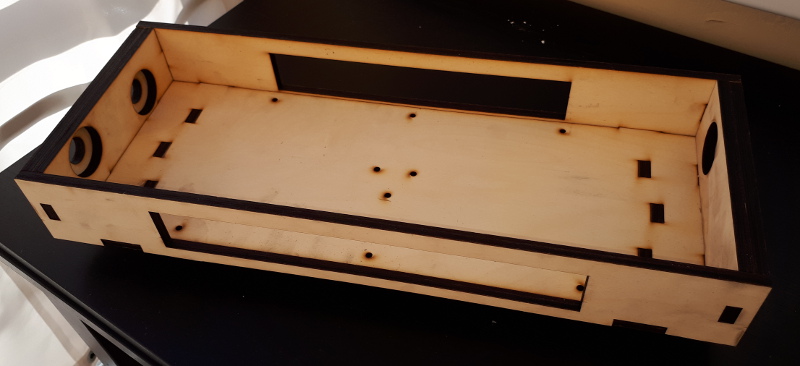
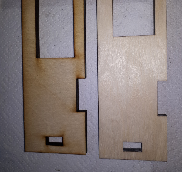
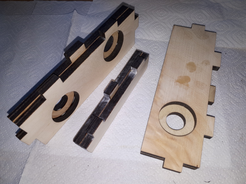
Trying to assemble - checking if all sizes are correct:
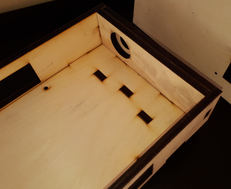
Pitch antenna side:
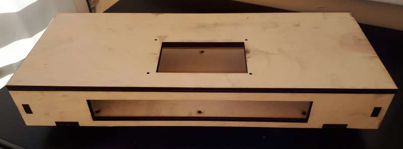
With cover:
Polish surfaces to remove burned stains:
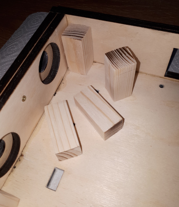
Glue side walls and legs:
Glue angle details on cover for centering cover:
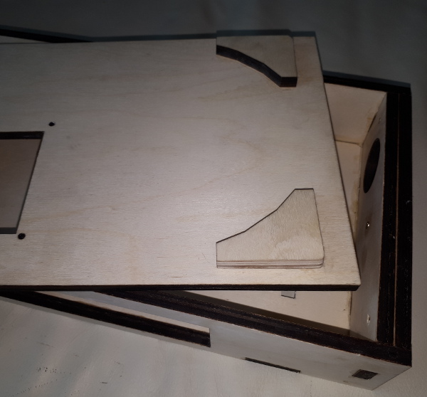
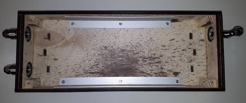
Wooden bars at corners to screw cover to:
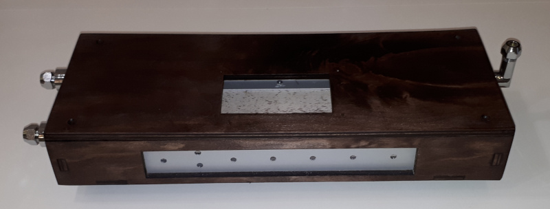
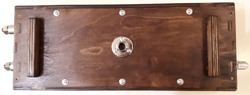
Assembled and polished. Comparing with Etherwave.
Dark color, varnished:
Designing front and back panels
Use aluminum angle profile 40x20x2mm.
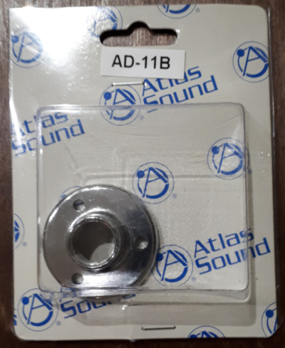
Mic stand mount
Use 3/8" mic stand mount from Atlas Sound:
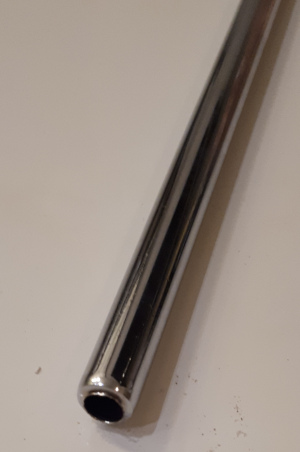
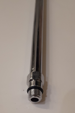
Mounting antennas
Cabinet has holes for 1/2" mounts.
Use fittings for 10mm 50cm chromed copper/brass water pipes.
Mounting Waveshare 4.3" LCD on cabinet cover
TODO...