Sensor Interface - fo-am/sonic-kayaks GitHub Wiki
As the Raspberry Pi cannot on it's own read analogue voltages from the turbidity sensor, we use an Arduino to do this for us. As the Arduino is also capable of reading the other sensors, we use it as a hub to collect data to pass on the the Raspberry Pi. This also has the side effect of freeing up interfaces on the Pi to (for example) use more advanced GPS units.
We decided to use strip board to construct the sensor interface rather than design a bespoke PCB design for various reasons:
- It allows a flexible circuit that can be modified to add new sensors later (as we ended up doing).
- Other people following this guide can easily customise it to their needs.
- The tools and materials are easily obtainable.
Tools required:
- Wire cutters/stripper
- Strip board track cutting tool (or small drill bit)
- Soldering iron and solder
- Heavy duty knife for trimming the strip board
- USB cable for programming the Arduino
- Multimeter for testing
- Clear nail varnish
Ingredients:
- Strip board (£1.27)
- Indicator LED (£0.11)
- 1 10KΩ resistor (£2.37 for 230 piece resistor kit)
- 1 4.7KΩ resistor
- 2 100Ω resistors
- 2 100nF ceramic capacitors
- 2 15 way header sockets (£0.68)
- 3 4 way header pins (£0.32 for 36 way strip)
- 1 3 way header pins
- Thin insulated single core wire (a bit easier as it doesn't fray when pushing it through the strip board and cause short circuits) (£0.26)
- Arduino Nano (you can use any version 3 or above, including Nano Every) (£4.28)
(The header pins/sockets are commonly known as "Dupont" but are actually "Mini-PV", try searching for either.)
Total cost for materials from e.g. Bitsbox: £9.29
Instructions
-
Trim a 20X20 hole/track area of strip board. The easiest way to do this is to score the board with a heavy knife to cut through the tracks, then snap it on a straight edge.
-
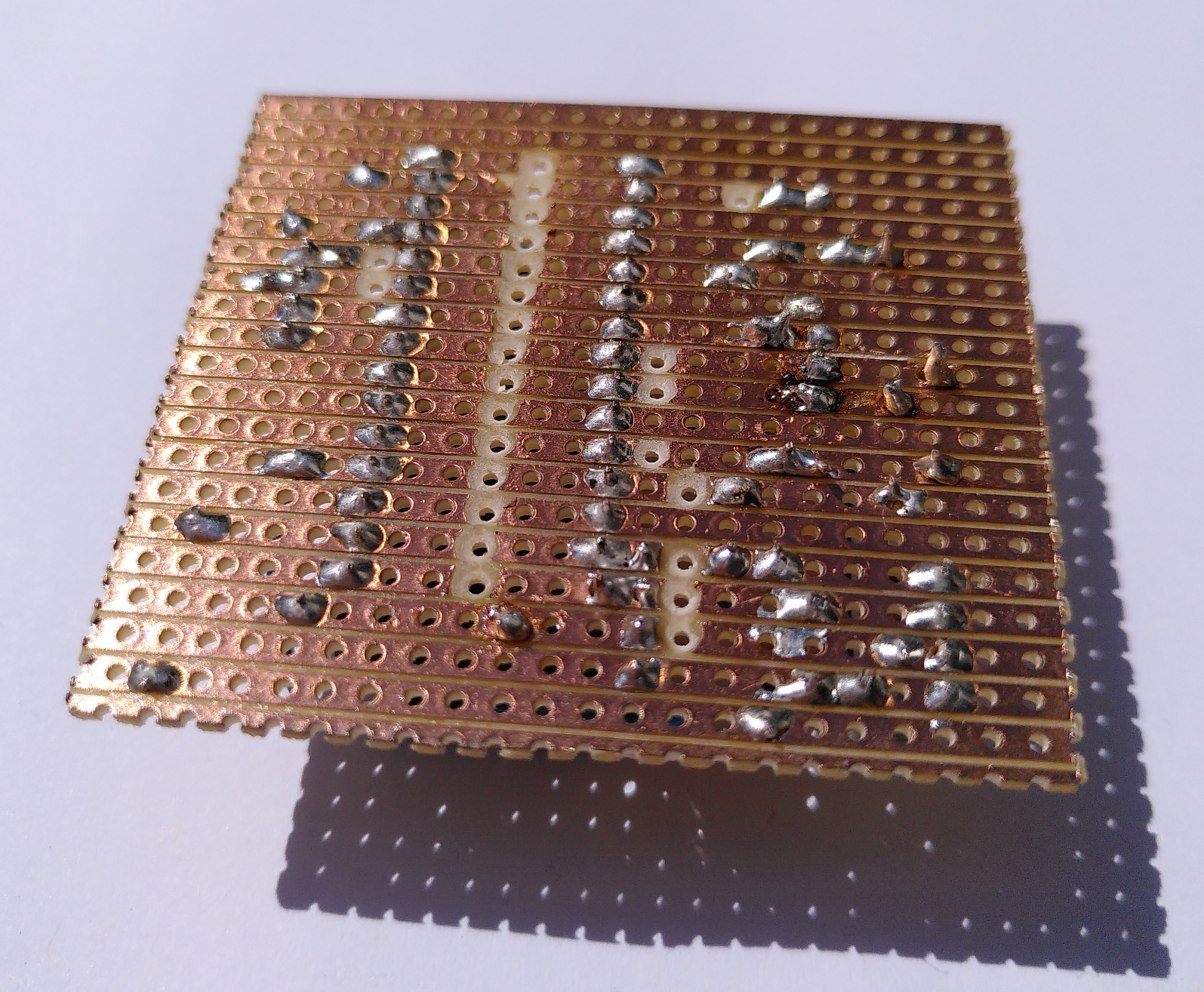
Cut the tracks as described in the plan. The track numbers help to stay sane - this board has been flipped to show the underside.

-
Clean the board from copper debris and test that the cuts have actually isolated the electrical connection, there are always some that don't for me. Recut any that need it and re-test.
-
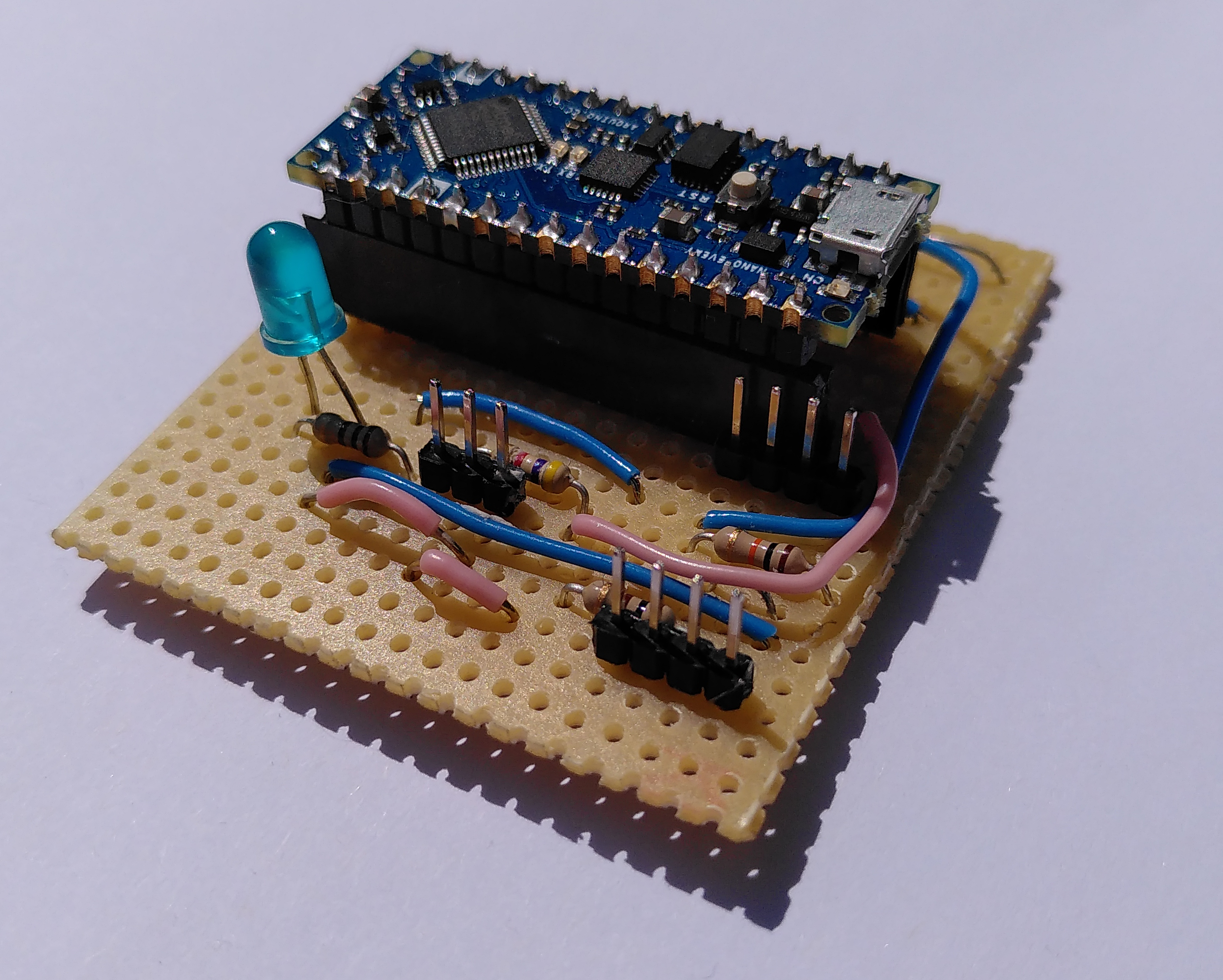
Solder components as indicated. I like to start with the header sockets for the Arduino to get myself oriented, then the smaller components, resistors, header pins and finally wire it together. The Fritzing project can be found here.

When done it should look something like this:
- Check with the multimeter that there are no solder "bridges" between tracks etc. The more testing you can do saves so much time later on.
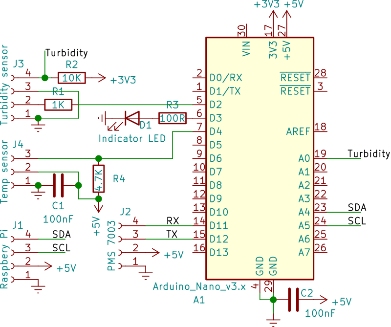
For completeness, this is the circuit schematic for the PCB:
-
While still disconnected, plug in the Arduino to your computer and program it using the Arduino IDE (it might work with the web version, I haven't tried that) with this sketch. It's probably easiest to download the whole repo and load it from there.
-
Disconnect the Arduino and plug it into it's sockets (these means you can remove it and use it for other projects). Check it works by plugging it in via USB again. The LED should flash 10 times to indicate that it is happy - you don't need to plug in any of the other sensors to run this check.
-
I've found it's important to treat the board to prevent corrosion - this is particularly the case as even though it'll be in a waterproof box, we are going to be using it in a kayak on the sea! Clear nail varnish can be applied to coat the soldering and tracks - it is also possible to solder through this but it burns away the varnish so I only recommend doing this once its been tested.
Connecting to the Raspberry Pi
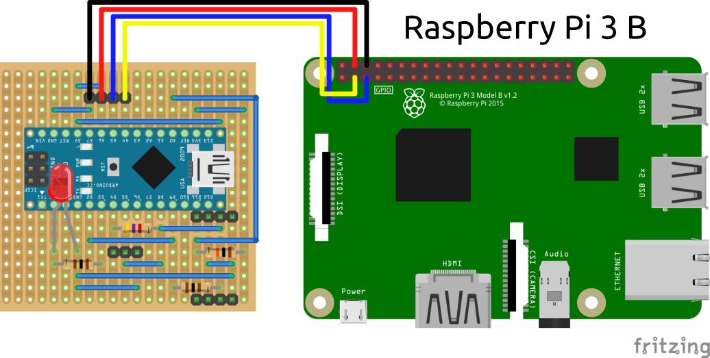
All the sensor data is passed to the Raspberry Pi for realtime sonification and storage for later analysis. This is done using an i2c serial connection, which only needs two wires. Another two connections are needed to provide 5V power for the interface and sensors, which all plug into the 4 pin header connector at the "top" of the board.
You can simply use 4 (socket to socket) jumper connectors to provide this connection, or you can build a custom connector with the same 4-core cable used for the rest of the sensors. The advantage of a custom cable is that you can build one that plugs into the Pi GPIO that won't require remembering which pins are which.