BlueSCSI 1.1 Desktop Assembly - erichelgeson/BlueSCSI GitHub Wiki
[!IMPORTANT] If you are looking for BlueSCSI v2 documentation please go here: https://github.com/BlueSCSI/BlueSCSI-v2/wiki
1.1 Desktop Assembly (document a work in progress)
Before you start
Read through all instructions before starting.
Verify you have all the components
- Preprogrammed STM32 BluePill with 2x 20 pin headers
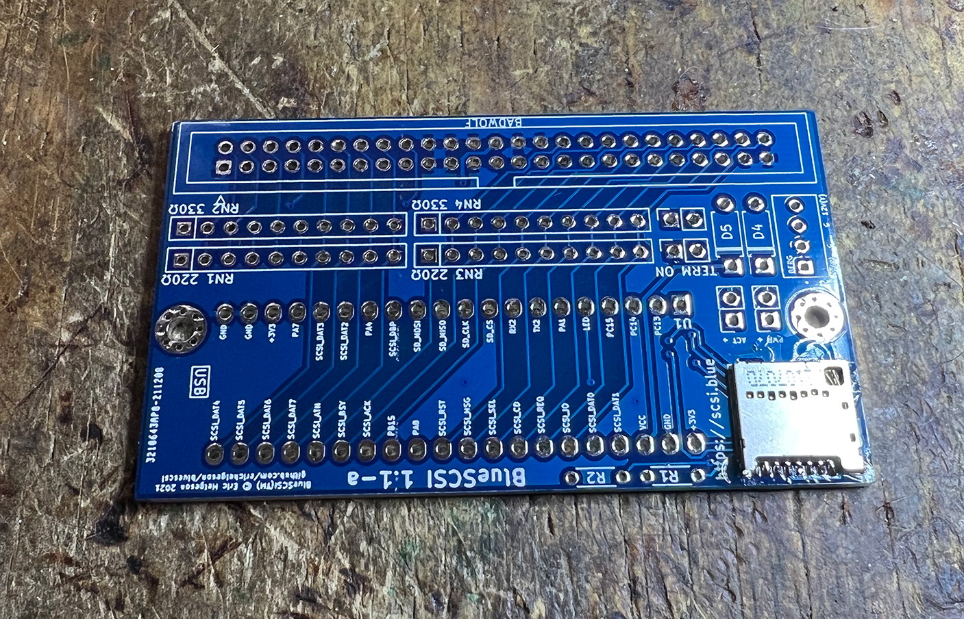
- BlueSCSI 1.1 desktop PCB
- 50 pin male SCSI connector
- 2x Diodes
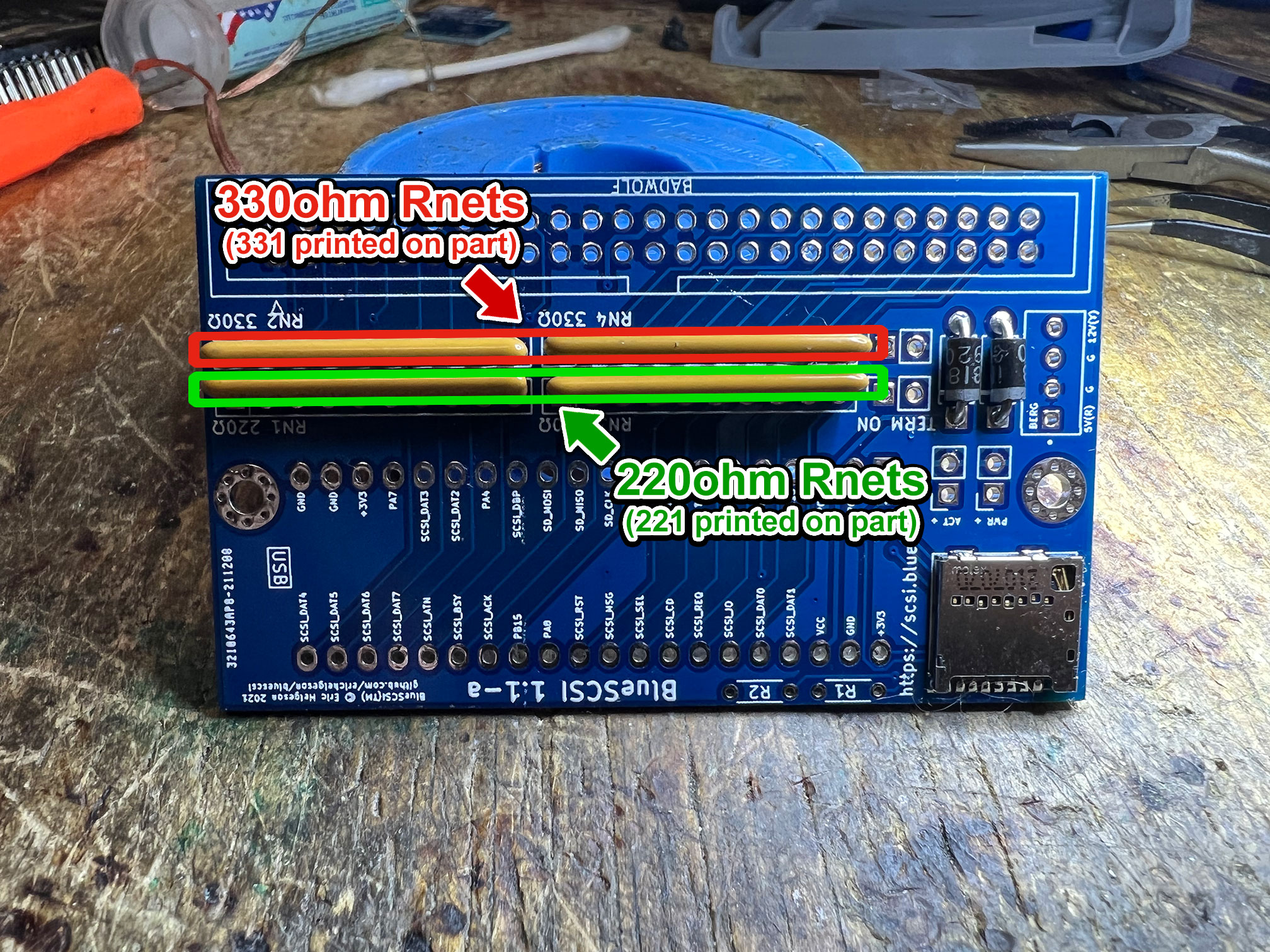
- 2x 220ohm Resistor Networks
- 2x 330ohm Resistor Networks
- MicroSD Socket
- Berg connector
- 2x 2 pin headers with jumpers
- 2x 2 pin headers for LEDs (optional)
- 2x 330ohm 1/8w resistors for LEDs (optional)
- 3d printed bracket
Videos
None yet
Building
- Solder the surface mount SD Card holder onto the board. Use the Drag Solder technique
- Once on, check continuity of all connections. Fixing this after the BluePill is on will be difficult.
- Ensure the SD card fits and you don't have too much solder on the sides or contacts - if you do, you can use solder wick to clean some off
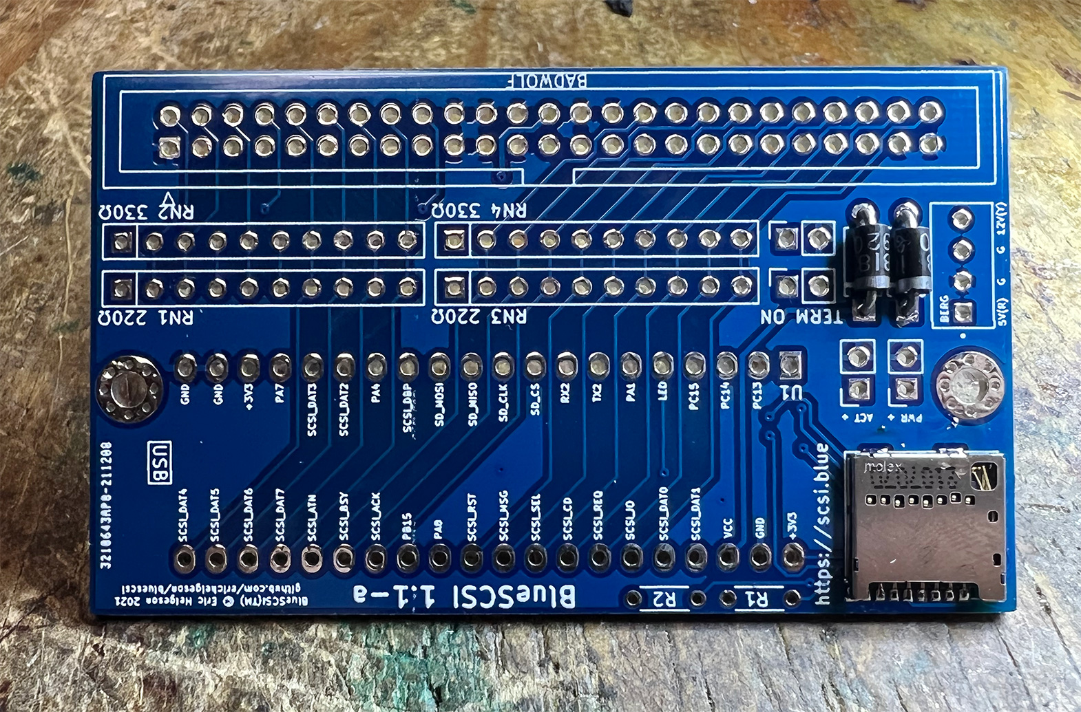
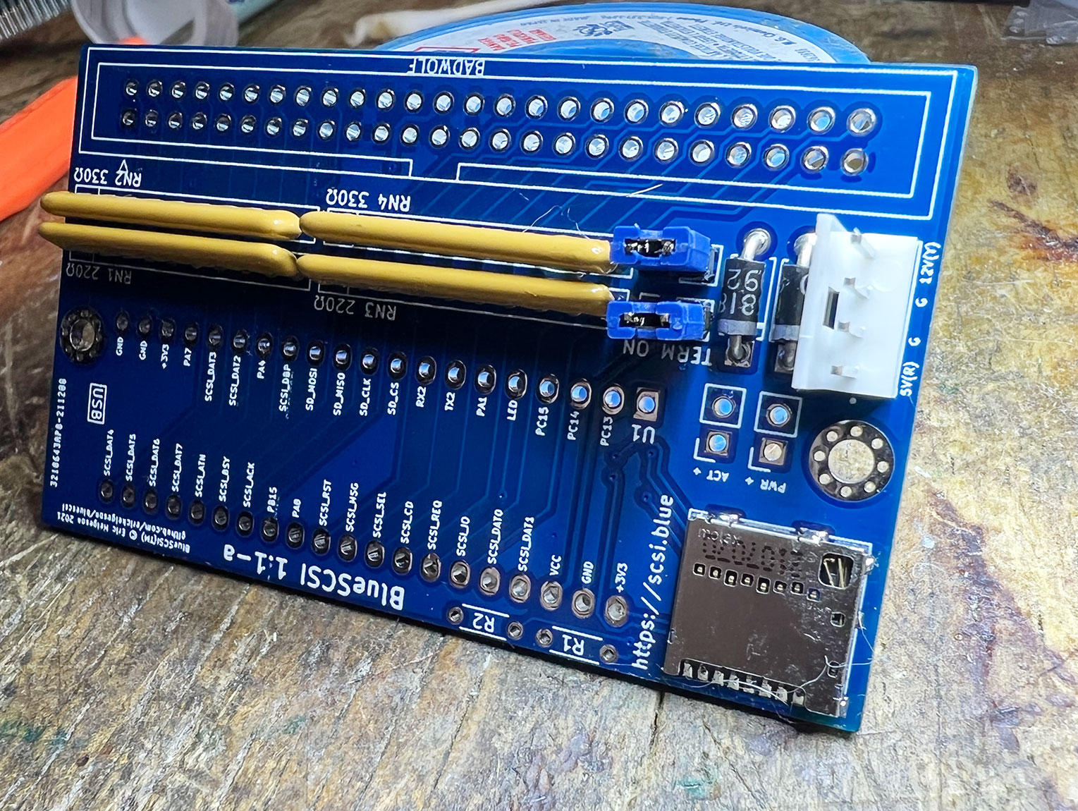
- Solder the 2 diodes to the board, ensure it is as flush with the PCB as possible. Match the stripe orientation with the silk screen printing on the PCB. Trim the excess legs.
- Solder on the resistor nets ensuring correct placement and orientation.
- Note: Pin 1 on the resistor nets is denoted with a dot. That must line up with the square silk screen on the board denoting pin 1.

- Solder on the Termination Jumpers & place the jumpers on to enable Termination
- Solder on the berg connector. This is only needed if your machine does not supply enough power via the SCSI bus, but it is recommended to solder it on if you have the connector.
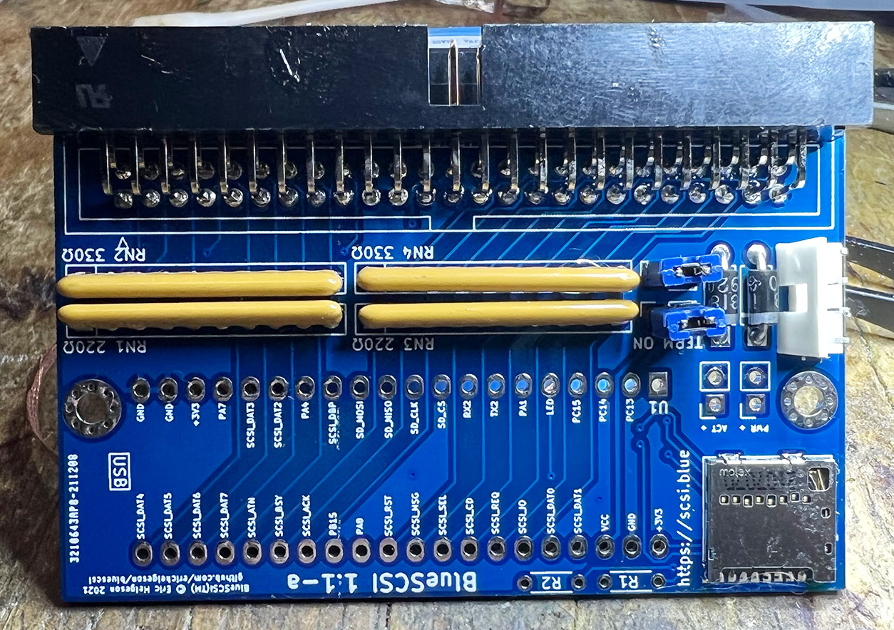
- Solder the 50 Pin headers on.
- Note Pin 1 and Box header on the silk screen.
-
Optional - solder on the two resistors for the LED (for both power and activity).
- Note, resistors may be a tight fit if you use a resistor greater then 1/8w size. Bend leg under the resistor if needed.
- Note, resistors have no polarity so can't be installed backwards - if you put them both the same way it looks a bit neater.
-
Optional - Solder on 2 pin headers for the LED
- Careful not to burn yourself! You can temporarily use the termination jumpers to hold the header in place while soldering to avoid touching the hot pins of the headers. Be sure to remove the jumpers from the LED header pins afterwards!
-
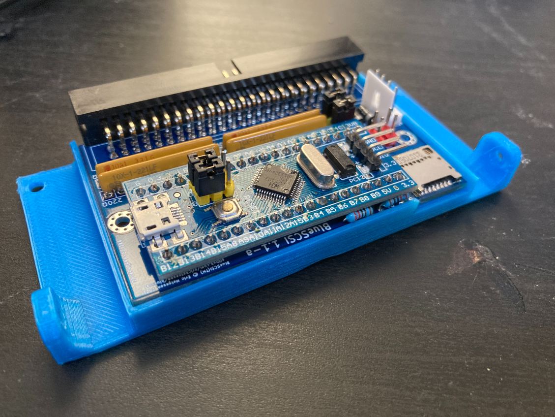
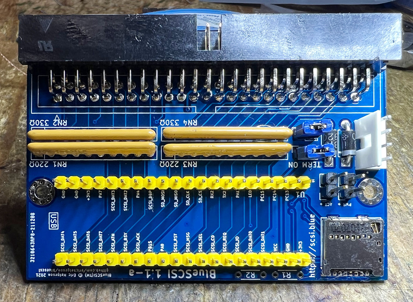
Solder the header pins on to the BluePill. Then solder the BluePill pill to the BlueSCSI PCB.
- Correct orientation is having the USB connector of the BluePill facing AWAY from the SD holder.
- NOTE: Consider adding headers to the board if you would like to have the BluePill removable.

- Place the BlueSCSI in the case.
- Configure it
- Test it! Plug it into your favorite Mac, run a benchmark with SCSI Director Pro, play some Lemmings, write a document in ClarisWorks, enjoy!
Built