BlueSCSI 1.0 a b c Assembly - erichelgeson/BlueSCSI GitHub Wiki
[!IMPORTANT] If you are looking for BlueSCSI v2 documentation please go here: https://github.com/BlueSCSI/BlueSCSI-v2/wiki
BlueSCSI 1.0 A/B/C Assembly
Before you start
Read through all instructions before starting.
Verify you have all the components
- Preprogrammed STM32 BluePill with 2x 20 pin headers
- BlueSCSI 1.0 PCB
- 2x Diodes
- 50 pin male SCSI connector
- 2x 220ohm Resistor Networks
- 2x 330ohm Resistor Networks
- MicroSD Socket
- Berg connector
- 2x 2 pin headers with jumpers
- 3d printed bracket
Videos
Assembly videos created by the community so far
Stephen Arsenault - BlueSCSI Kit Assembly 2:52
Joe's Computer Museum - A New Challenger - BlueSCSI - #MARCHintosh Review 26:52
Geeky Bit - Tutorial - BlueSCSI Assembly 20:35
Building
-
Solder the surface mount SD Card holder onto the board. Use the Drag Solder technique
- Once on, check continuity of all connections. Fixing this after the BluePill is on will be difficult.
- Ensure the SD card fits and you dont have too much solder on the sides or contacts - if you do, you can use solder wick to clean some off
-
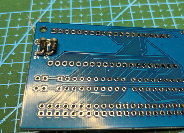
Solder the diode to the bottom of the board, ensure it is as flush with the PCB as possible. Trim the excess legs
-
Solder the header pins on to the BluePill. Then BluePill pill to the BlueSCSI PCB.
- Correct orientation is having the USB connector of the BluePill should be over the SD Card holder.
- NOTE: Consider adding headers to the board if you would like to have the BluePill removable.
-
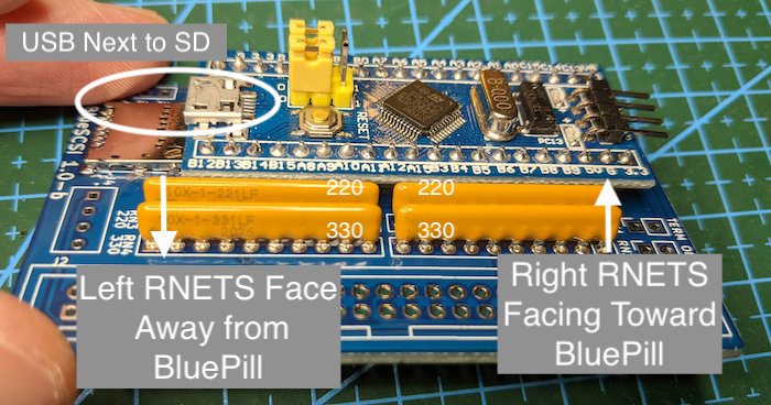
Solder on the resistor nets. Pin one is marked on the board and the resistors.
- 220 RNETS (RN1 & RN3) are closest to the BluePill - NOTE PIN one on each - they are opposite of eachtoher. See photo.
- 330 RNETS (RN2 & RN4) are furthest from the BluePill - NOTE PIN one on each - they are opposite of eachtoher. See photo.
-
Solder on the Termination Jumpers & place the jumpers on to enable Termiation
-
Solder the 50 Pin headers on.
- Note Pin 1 and Box header on the silk screen.
-
Solder on the berg connector. Only needed if your machine does not supply enough power via the SCSI bus, but recommended to solder on if you have the connector
-
Not recommended anymore - Solder on the debug headers near the SD card. Only needed for debugging, requires a special firmware. Headers have been removed from the new PCB revisions
Fully Assembled

- Configure it
- Test it!
- Plug it into your favorite Mac, run a benchmark with SCSI Director Pro, play some Lemmings, write a document in ClarisWorks, enjoy!
Version 1.0-b & 1.0-c BOM
-
Mouser Cart
-
Parts
- STM32F103C8T6 (U1) aka BluePill board.
- 2x 330 (RN2, RN4) Resistor nets https://www.mouser.com/ProductDetail/652-4610X-1LF-330
- 2x 220 (RN1, RN3) Resistor nets https://www.mouser.com/ProductDetail/652-4610X-1LF-220
- 2x Diodes https://www.mouser.com/ProductDetail/583-1N5818-T
- SD Card Holder (J1) https://www.mouser.com/ProductDetail/538-104031-0811
- Headers https://www.mouser.com/ProductDetail/872-920-0011-01
- 50 PIN SCSI header https://www.mouser.com/ProductDetail/517-30350-6002/ - May substitute with 2 rows of headers from above.
- Floppy/Berg Power header https://www.mouser.com/ProductDetail/571-1718254 (Optional)
Note on Right angle connectors - Right angle connectors are not notched the correct way, PCB rev 1.1 fixes that Optional