Hardware - ejbergdk/loconet-routectrl3 GitHub Wiki
Required hardware
The Route Controller v3 software has to run on an AVR DA (or possibly DB) processor, as the low level Loconet code uses their inbuilt configurable logic, not available in other AVR's. There are two ways to make the hardware:
1: Full do-it-yourself
If you already have a suitable AVR programmer and prior experience with making circuits involving AVR's, you could make your own hardware. I have a small reference design using an AVR128DA28 on my homepage. That page also has an in-depth description of the inner workings of the AVR with regard to how it helps interfacing to Loconet.
2: Use a development board
If you are not up to making everything from the ground up, I can recommend the AVR128DA48 Curiosity Nano evaluation kit. It has an integrated programmer/debugger and a USB serial connection. You'll still have to solder on a few resistors and one transistor, or use it in a solderless breadboard.
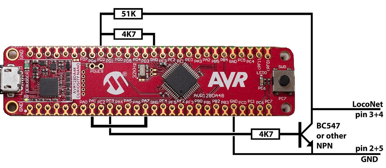
You'll need two resistors of 4K7 (4.7 kOhm) and one resistor of 51K (51 kOhm). One general-purpose low-power NPN transistor is also needed. I use a BC547B as they are widely available in Europe. In the US a 2N2222 or 2N3904 is probably easier to get your hands on. Remember to make a connection between PA1 and PA7.
With the development board solution, you need to have the USB cable connected to power the board. It isn't supplied from Loconet.
Optional hardware
Non-volatile RAM
Current signal and switch states can be handy to know sometimes. Unfortunately, there isn't a universally supported way to query this information over the LocoNet bus. This Route Controller keeps track of all signal/switch states locally. However, this information is lost at power down, so any information isn't valid until the signal/switch in question has been addressed at least once after power up.
The AVR's internal EEPROM could in theory be used to remember the signal/switch states, but as it has a relatively limited write duration, it would be worn out in less than a satisfactory time frame. Instead the Route Controller supports two other non-volatile memory options, EERAM and FRAM, that can be used to store the signal/switch states.
EERAM
EERAM is like a standard SRAM and an EEPROM melted together. As long as power is on, you can write as much as you like to it. It won't wear it out. Once power is lost, it automatically writes all its data to the EEPROM part. This way it only uses up one write cycle per power cycle, and with an estimated lifetime of more than one million write cycles, this should be more than enough for most uses.
Supported EERAM are: 47C04 and 47C16 for 5V circuits, and 47L04 and 47L16 for 3.3V circuits.
They connect to the AVR via I2C bus on pins PA2 and PA3.
FRAM
FRAM (or ferroelectric RAM) is another non-volatile memory type. It has a "limited" number of operations, but as that is in the order of a trillion (per memory cell), I'm sure it'll last long enough.
Supported FRAM are: MB85RC04, MB85RC08, MB85RC64, MB85RC128 and MB85RC256V.
Adafruit has this one, if you want one on an easy to use breakout board.
Just as with the EERAM, these also connect to the AVR via I2C bus on pins PA2 and PA3.
Enable use of non-volatile RAM
If you connect an EERAM or FRAM to the Route Controller, you need to enable support for it in the software.
You must define the symbol "NVRAM" among the other preprocessor macros. See here for more details.
If you use the FRAM MB85RC04 or MB85RC16 specifically, you must also add the symbol "NVRAM_BYTEADR", as these two use a slightly different addressing scheme. Do NOT add this symbol if you use any of the other supported EERAM or FRAM chips.