Manual PLC control - easymetal/Korrostop4.0-EN GitHub Wiki
PLC Connection
PLC means Programmable Logic Controller. Korrostop4.0 supports 2 digital Outputs that can be connected to a PLC or any kind of electronic. With the screen Config / PLC the behaviour of this two channels can be configured.
This Chapture describes, how you can connect and configure this feature.
Hardware
Internal Circuit
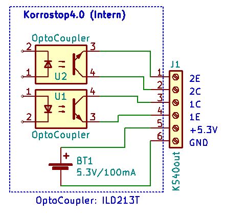
Korrostop4.0 have two potential free connections, that means four pins where you can connect your hardware. Every connection allows a maximum of 20 milli Ampere current and 70 Volts (details you will find here). There are also two pins connected to the internal Power Source. They supply 5.3V with a maximum of 100 mA current. There is no over load protection. Here you see the Schematic of the internal circuit:
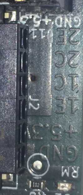
The following photo show the physical Connector:
Connect LED
A small demo to show, how to connect LED to Korrostop4.0.
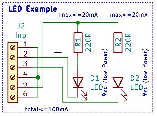
BOM:
- 2 x LED RED LOW POWER
- 2 x Resistor 220 Ohm / 0.125W (Red, Red, Brown and Silver or Gold)
- Some Wires
Connect Low Power Relays
If you do not need strong Relay you see here how to work with Low Power Relays.
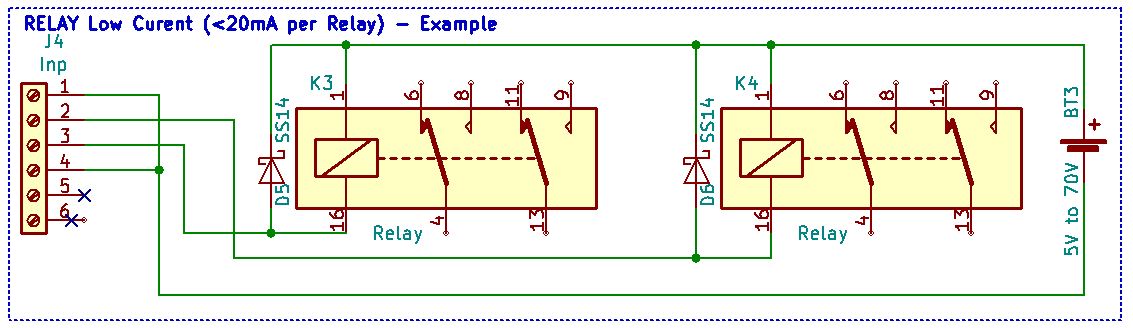
BOM:
- 2 x Diodes for removing reverse pulse
- 2 x Relay 4.4 to 5V / <=20mA (Input)
- External power source
- Some Wires
Connect Stronger Relay
For more power, you will find this example useful.
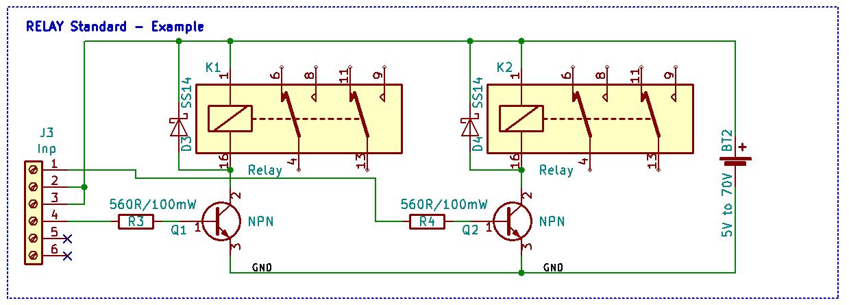
BOM:
- 2 x Diodes for removing reverse pulse
- 2 x Relay (user defined)
- 2 x Resistor 560 Ohm / 0.125 W (Green, Blue, Brown and Silver or Gold)
- 2 x Transistor NPN (user defined)
- External power source
- Some Wires
Connect Relay Modules
You also will find small modules called break out boards, that will do an excellent job for a small price.
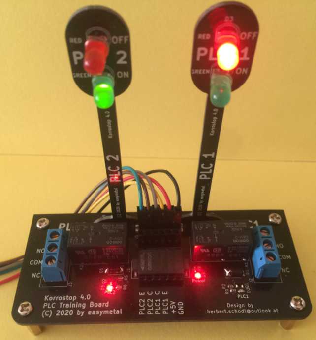
The easymetal internal training board
This is the schematic for our internal test and training board. There are some diodes and relays for testing and training. It has the look of a tiny traffic light.
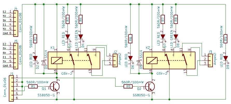
The total current for this schema is more than 100 mA (about 240 mA). This can NOT be used for production system. The reason is, that we do not use the WiFi and LAN combined with this training board. In this scenario, we use less current internally.
BOM:
- 2 x K1,K2: DIP-16_W7.62mm_Socket_LongPads, G5V-2
- 2 x D1,D5: D_SMA, SS14
- 3 x D2,D6,D9: LED_0603, LED RED
- 2 x D3,D7: LED_D5.0mm, LED RED
- 2 x D4,D8: LED_D5.0mm, LED GREEN
- 1 x J1: XW4L-06A1-H1, Conn_01x06|XW4L-06A1-H1
- 2 x Q1,Q2: SOT-23, SS8050-G
- 9 x R1,R2,R3,R4,R5,R6,R7,R8,R9: R_0603, 560R/100mW
- 2 x J4,J5: Pin_Header_Straight_1x06_Pitch2.54mm, Conn_01x06
Configuration
There are two possibilities to configure then PLC Output:
- Bind it to the Colour Schema. Binding to the Colour Schema means that you can configure your system to set your output for a channel to high, if there is a specified colour for Output, Input Korrostop, Temperature or Flow.
- Bind it to Telemetry. Binding to Telemetry means that you can configure your system to set your output for a channel to high, if a specified value for Output, Input Korrostop, Temperature or Flow. is measured.
You can make this decision for every channel in depended.
Binding your external signal to the Colour Schema have the benefit, that you have straight forward rules for your colour symbolic. And it is easy to configure. The trash holds for the colour can be configured for the screen and your external signal at Configuration / Alarm.
If you bind your external signals to Telemetry you have more control to the behaviour. But it is a little bit more complex to configure it.
But both alternatives are configured with the same screen. Enter your expression for one or both channels. If the expression is too large for text box, you can split it in to parts. Internal they are connected to one string.
Expressions
Colour Binding
Basic example:
For PLC1: (get("telemetry","flow_color")!=GREEN)&(("telemetry","condin")>5.0)
For PLC2: get("telemetry","condout_color")=RED
With the function get you can access internal values. It needs two parameters: The Domain and the key as string. Our Domain is “telemetry” and the key "condout_color". The Operator = is a Boolean operator and compares the internal constant YELLOW with the returned value of the function get. If this is true, the output will be triggered.
Possible constants, parameters and operators:
Telemetry Colour Parameters:
condin_colorConductance for incoming Watercondout_colorConductance for outgoing Watertempwater_colorTemperature of waterkorrostop_colorPercent usage of IONISERflow_colorWater flow
Operators:
=Equal!=Not Equal
Colour Constants:
REDfor Red ColourYELLOWfor Yellow ColourGREENfor Green ColourCOLORNONEin very rare cases where no colour can be calculated
Telemetry Binding
Basic example:
For PLC1: get("telemetry","condout")<1
For PLC2: get("telemetry","condout")>5.2
It looks very similar to the colour binding example but “_color” is missing and it the comparison is with a number. Also the equal operator has change.
There is a very useful function for comparing values and avoid flickering: Trigger
Syntax: bool trigger(bool currentstate, number value, number minthreshold, number maxthreshold)
For further information see this chapter.
Possible parameters and operators:
Telemetry Parameters:
condinConductance for incoming Watercondin_max_valueMax Conductance for incoming Watercondin_min_valueMin Conductance for incoming WatercondoutConductance for outgoing Watercondout_max_valueMax Conductance for outgoing Watercondout_min_valueMin Conductance for outgoing Waterflow_pertimeWater flow per timeflow_volumeWater flow totalkorrostopPercent usage of IONISERtempchipTemperature of internal chiptempwaterTemperature of watercounterEvery Telemetry Package (single Measurement) has a numberioniserConfigured IONISERsourceThe Telemetry Source (measure = 0, simulator = 1, sdcard = 2)nowCurrent Date Timecondin_min_timeTime when Min Conductance for incoming Water was reachedcondin_max_timeTime when Max Conductance for incoming Water was reachedcondout_min_timeTime when Min Conductance for outgoing Water was reachedcondout_max_timeTime when Max Conductance for outgoing Water was reachedsystem_start_timeblinkTrue if the Display is blinkingplc1Current Value of PLC Channel 1plc2Current Value of PLC Channel 2
Operators:
Math:
+Plus:1 + 2=>3-Minus:3 - 1=>2*Multiply:2 * 3=>6/Divide:7 / 2=>3.5%Modulo (Rest of Division):7 % 3=>1(Parenthesis):(1 + 2)=>3
E.g.: 2 + 3 * 4 => 14; (2 + 3) * 4 => 20;
Boolean:
!Not:! true=>false;! false=>true;! ! true=>true;&And:true & true=>true;true & false=>false;false & true=>false;false & false=>false;|Or:true | true=>true;true | false=>true;false | true=>true;false> | false=>false;
Comparison:
=Equal!=Not Equal<Less than>Greater than<=Less than or Equal>=Greater than or Equal
E.g.: ((1 < (5+3)) & (2>1)) | true => true
Other Bindings
Generally there can be used every function that evaluate to an Boolean Value. There are a lot of Functions, Constants and Language Constructs like if then else endif or user defined variables.
For further information see this chapter.