4. CONCEPT GENERATION (review 2) - e-division-2019-2020-odd/Repo-06 GitHub Wiki
Task 2.1: Formulate The Problem Definition by listing Constraints Functions An Objects
Problem Definition:
Design a bot for the students of age group 13-15 to showcase the mechanism of gaits of animals. The bot must be easy for the students to operate and easy to carry and must have a good battery backup. A bot having minimum four legs, and the bot must not weigh more than 2000 grams.The cost of the bot must be within 3000 Rupees and the size must not exceed 1x1x1 foot.
Task 2.2: List The Inputs, Outputs Of The System And Represent Black Box Model
Black Box
Task 2.3: List The Functions Of The System Shown In The Video.
| Sl. No | FUNCTIONS |
|---|---|
| 1. | Receiving instructions |
| 2. | Respond to commands |
| 3. | Walking |
| 4. | Sensing |
Task 2.3.1:
Function Tree
Task 2.3.3:
Morphological Chart
| Functions | Pantagraph Leg | Mammalian Leg | Pentograph leg | Simple two-link leg |
|---|---|---|---|---|
| 1. Input commands | Buttons  |
Bluetooth  |
IR Remote control  |
Arduino  |
| 2. movement | stepper motor  |
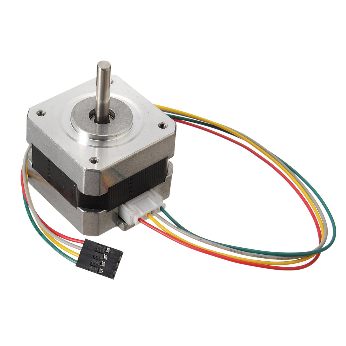
DC motor  |
AC motors  |
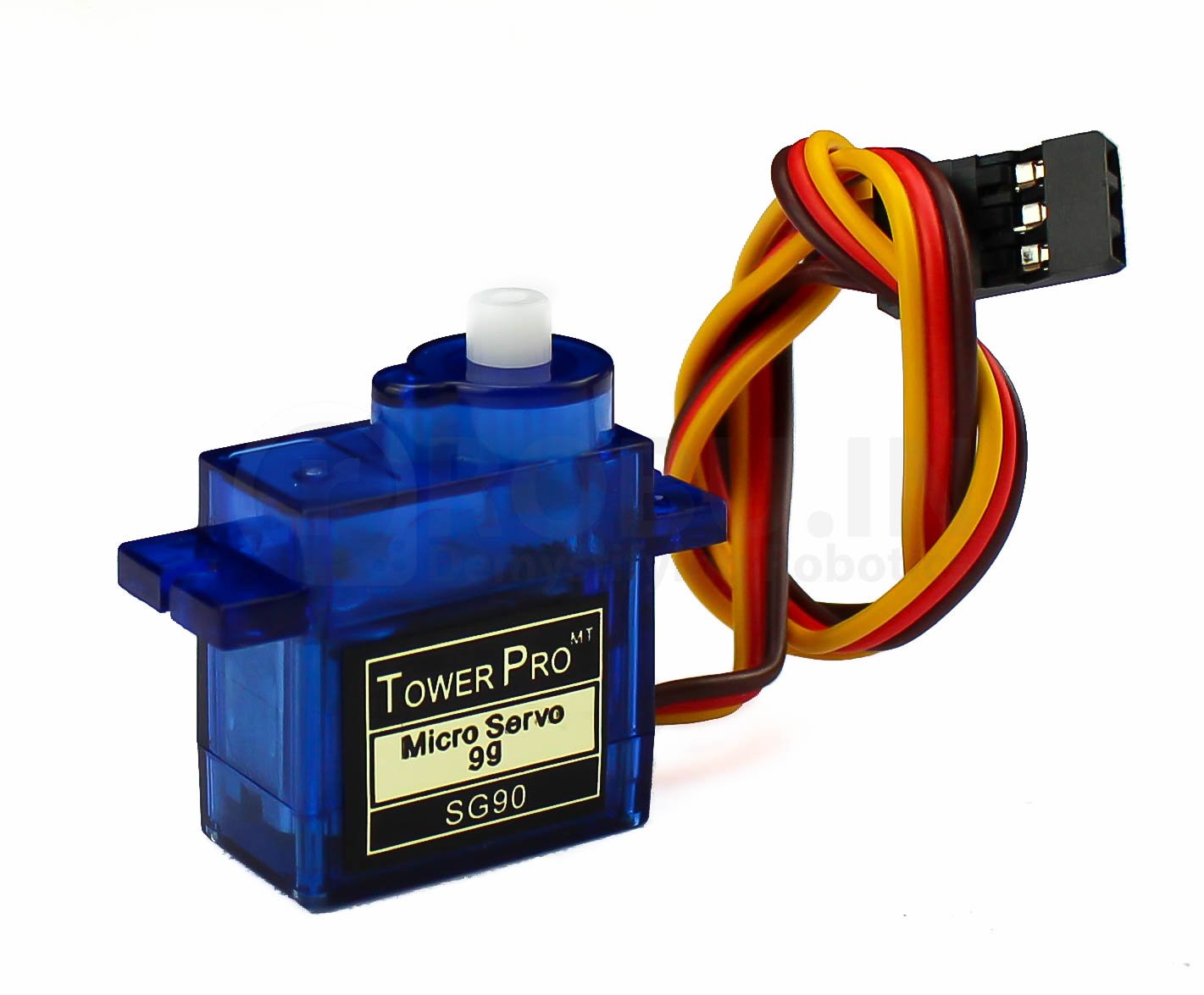
Servo motors  |
| 3. Type of Movement | Galloping | Crawling | Rolling | Walking |
| 4. Sensing | Ultrasonic sensor  |
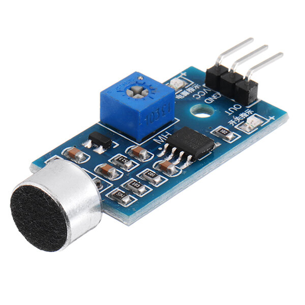
Voice command  |
Touch sensor  |
IR sensor  |
Sub Functions
| SUB FUNCTIONS | ||
|---|---|---|
| Steps | User actions | System Behavior |
| 1. | Switch on (power supply) | The bot is turned on |
| 2. | Commands to move ahead | the signal is sent to the processor |
| 3. | The motors get turned on | |
| 4. | The bot lifts its legs | |
| 5. | The bot places its leg forward or backward | |
| 6. | The bot moves in a specific direction | |
| 7. | Direction commands | Change in direction of walking |
| 8. | Move forward | |
| 9. | Move backward | |
| 10. | Move left | |
| 11. | Move right | |
| 12. | Movement of limbs to generate signals(data) | |
| 13. | Commands to change speed | The speed varies |
| 14. | the bot moves fast or slow | |
| 15. | Obstacle sensing | Sensing of the presence of obstacles |
| 16. | Sensing of the shape and size of obstacle | |
| 17. | Acknowledgment indicating obstacle | |
| 18. | The bot pauses and changes its direction | |
| 19. | Switch off | The bot is turned off |
Task 2.3.2: GLASS BOX

Designs
Design 1
1. Pentagraph leg
A pentagraph, or five-bar mechanism, has been used in other robotic applications to provide mechanical transparency of a linkage structure. By situating the actuators at a central base and using light members, the dynamic effects of the mechanism can be minimized while still providing structural rigidity.The planar five-bar mechanism could be used to position the leg shaft in a plane. The shaft or the entire leg platform could then be controlled to provide motion in the third axis.
Design 2
2. Mammalian Leg
The entire leg swings about the hip joint to advance and retract the leg while the angle of the knee joint is controlled to lift the foot out of the way during the advance phase. The leg can be designed using a four bar linkage structure with one of the links being of variable length.
Design 3
3. Simple two-link leg
This design consists of two links connected through a knee joint. The walking motion is accomplished by controlling the angle of the two links to position the end effecter, or foot. The entire leg is mounted on a swiveling base in order to advance and retract the leg.
Design 4
4. Pantograph Leg
The pantograph mechanism consists of a simple four bar parallelogram mechanism. This simplifies the kinematics associated with the mechanism and thereby reduces the computational complexity of the control