CP calibration - dzurikmiroslav/esp32-evse GitHub Wiki
Control pilot calibration is performed by setting the right pilot.levels values in board.yaml.
These values are used for detection EVSE states and diode short error.
Next table descibe J1772 specification pilot states. (source)
| State | High voltage | Low voltage | Frequency | Resistance |
|---|---|---|---|---|
| A | 12 V | N/A | N/A | N/A |
| B | 9 V | - 12 V | 1 kHz | 2.74 kΩ |
| C | 6 V | - 12V | 1 kHz | 882 Ω |
| D | 3 V | - 12V | 1 kHz | 246 Ω |
| E | 0 V | 0 V | N/A | |
| F | N/A | -12 V | N/A |
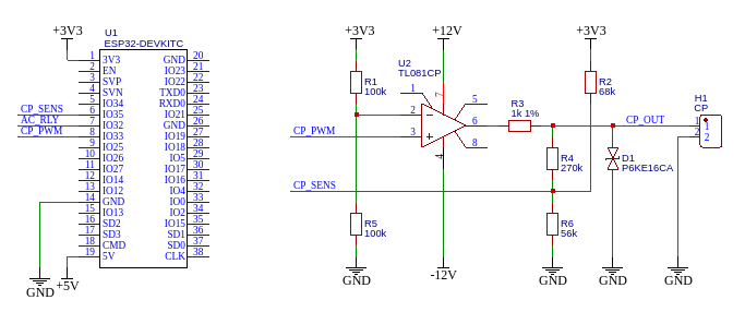
On following example circuit, sensing CP voltage is provided by voltage divider with shift (R2, R4, R6).
Wire CP_OUT is connected to the EV, CP_SENS is connected to ESP32 adc.
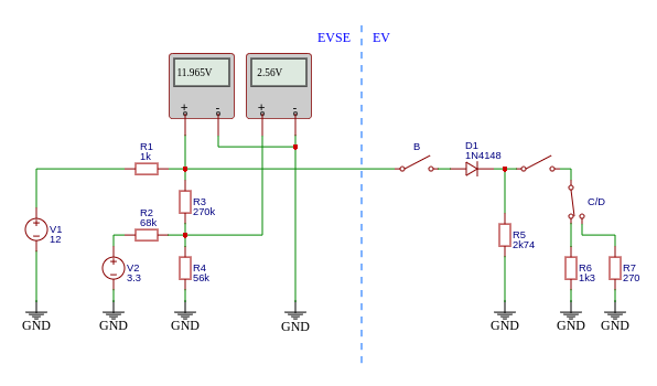
For this circuit there is simulation with EV side. Because state detection is performed only on high voltage, a DC power supply can be used in the simulation.
State A
State B

State C

State D

And negative voltage
For diode short detection, just detect -6V in the lower voltage.

In next table is measured values for EV states.
| State | ADC voltage |
|---|---|
| A | 2560 mV |
| B | 2251 mV |
| C | 1948 mV |
| D | 1636 mV |
| Low voltage | 728 mV |
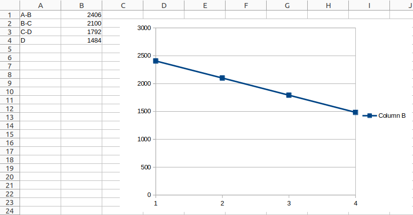
Next, calculate midpoint voltage between states, that will be used as down threshold. For state D, the value is calculated as a sequence of the difference B-C and C-D.
| State | Calculation | Down threshold |
|---|---|---|
| A-B | (2560 + 2251) / 2 | 2406 mV |
| B-C | (2251 + 1948) / 2 | 2100 mV |
| C-D | (1948 + 1636) / 2 | 1792 mV |
| D | 1792 - (2100 - 1792) | 1484 mV |
When the calculated values are displayed on the graph, they should have a linear course.
From these values board.yaml will look like this:
pilot:
  levels: [2406, 2100, 1792, 1484, 728]
Note When designing a new voltage divider, remember the ESP32 adc suggested range. (adc is configured for attenuation 11dB)