Extend IOP16 minimal example - douggilliland/IOP16 GitHub Wiki
This is a guide to extending the minimal IOP example by adding IOP16 Peripherals to the minimal design
- This is not the same as Embedding the IOP16 into another design
- This guide requires general familiarity with IOP16 16-bit I/O CPU Design
- This example does not cover porting to a different FPGA card
- Will need to adjust I/O pin assignments if a different FPGA is used
- Start with baseline (minimal) design
- Copy/clone baseline (minimal) design
- Build baseline (minimal) design
- Copy design to new folder
- Select/add peripherals
- Create new peripherals
- Write assembly code
- Build/test
Starts from minimal IOP example
- Similar to Arduino "Blink Sketch" and uses the following resources
- Timer Unit - 1 second timer
- The Timer unit can be removed if not needed
- Timer makes Blink easier
- On-board LED
- Timer Unit - 1 second timer
- Clone the two repositories to the same directory level since relative paths are used for source files
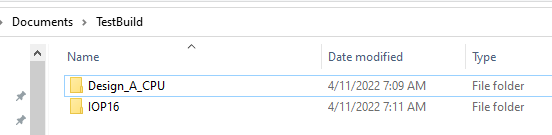
- Example copies files to TestBuild folder
- There are a lot of extra files in the two unzipped folders (380MB)
- Alternately you can download the two ZIP files from GitHub
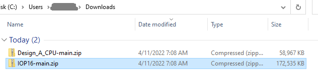
- Unzip these two folders into the same folder
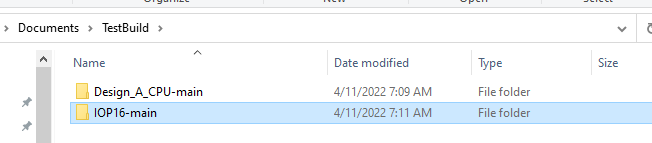
- Rename the folders to remove the -main from the folder path
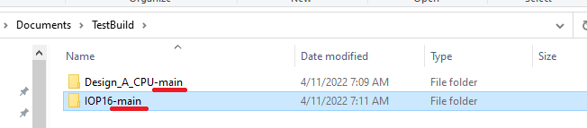
- Result
Start by building the minimal example in Quartus II
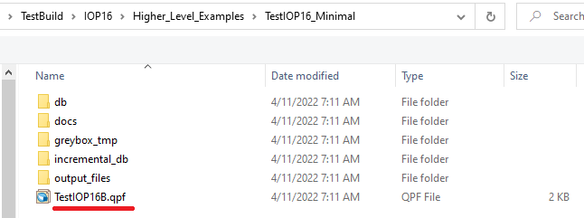
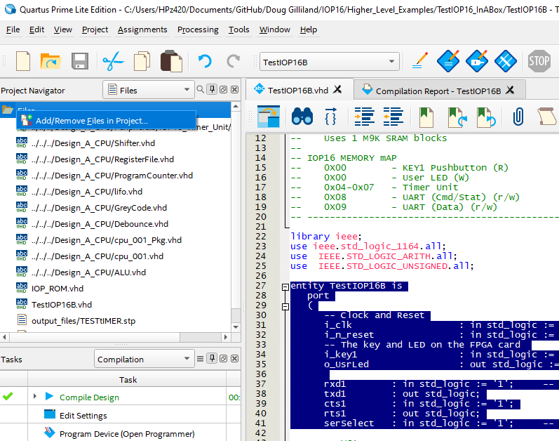
- Open the Project file (TestIOP16B.qpf) in Quartus II
- Relative path: ..\TestBuild\IOP16\Higher_Level_Examples\TestIOP16_Minimal
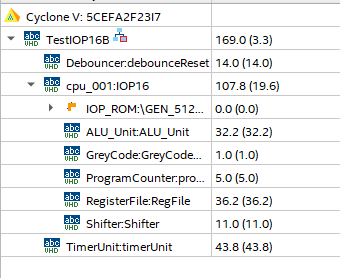
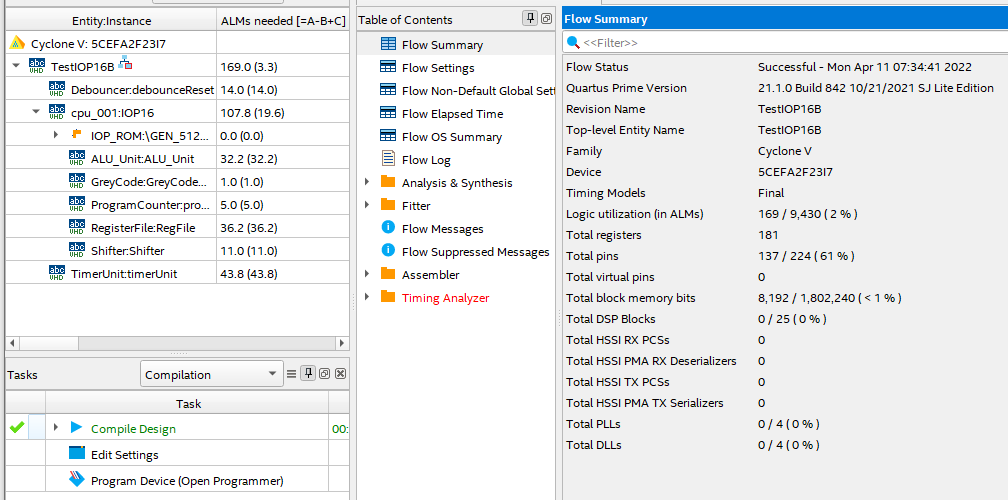
- Entities in Quartus should look like
- Build FPGA (click the blue "Start Compilation arrow)
- Quartus does not verify the ROM file was correct
- Could be buried in the status messages
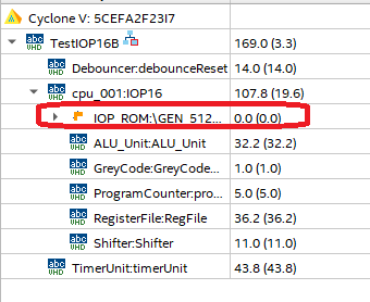
- Likely need to re-point to the ROM .MIF file since Quartus II sometimes "forgets"
- Double click on the IOP_ROM file
- Hit finish
- Check for error message
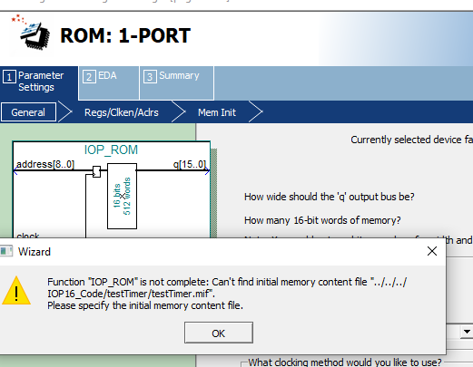
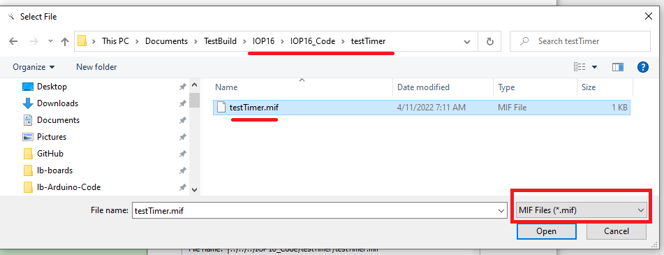
- Re-point to the ROM file
- Make sure to select .MIF file extension
- Build again
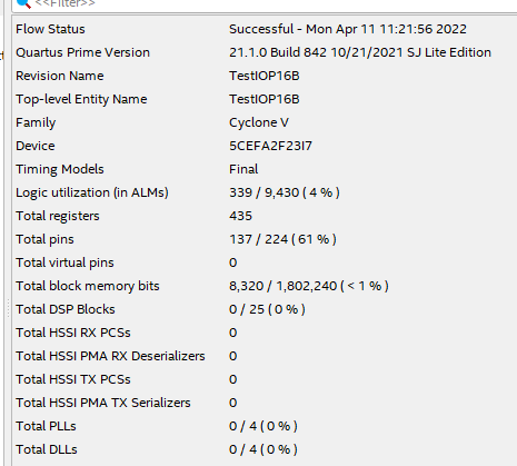
- Should be no error messages
- Result
- Download to FPGA
- Make sure pointing to the right folder
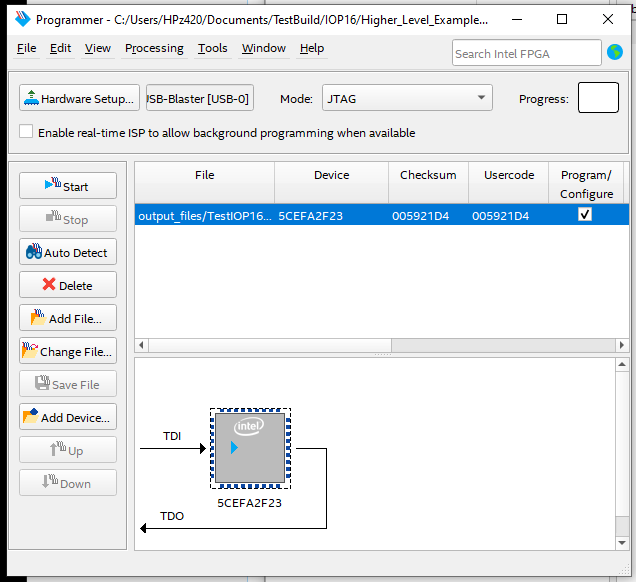
- User LED should be blinking
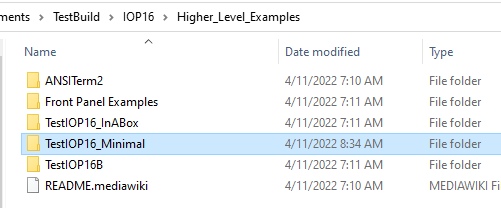
- Copy from folder ..\TestBuild\IOP16\Higher_Level_Examples\TestIOP16_Minimal
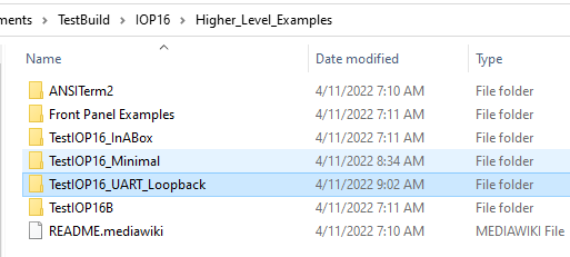
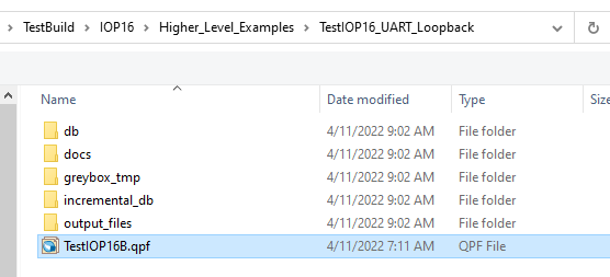
- Copy to folder ..\TestBuild\IOP16\Higher_Level_Examples\TestIOP16_UART_Loopback
- Build (as above)
- Make sure to update ROM file (as above)
- Make sure pointing to the right folder when downloading
- Test (as above)
- Pick from Supported peripherals list
- Update Memory map in comments at start of TestIOP16B.vhd to add UART addresses
-- IOP16 MEMORY Map
-- 0X00      - KEY1 Pushbutton (R)
-- 0X00      - User LED (W)
-- 0x04-0x07 - Timer Unit
-- 0X08      - UART (Cmd/Stat) (r/w)
-- 0X09      - UART (Data) (r/w)
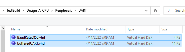
- Select VHDL files from \TestBuild\Design_A_CPU\Peripherals\UART folder
entity TestIOP16B is
  port
  (
    -- Clock and Reset
    i_clk     : in std_logic := '1';		-- Clock (50 MHz)
    i_n_reset : in std_logic := '1';		-- SW2 on FPGA the card
    -- The key and LED on the FPGA card
    i_key1    : in std_logic := '1';		-- SW1 on the FPGA card
    o_UsrLed  : out std_logic := '1';		-- USR LED on the FPGA card

    rxd1      : in std_logic := '1';		-- Hardware Handshake needed
    txd1      : out std_logic;
    cts1      : in std_logic := '1';
    rts1      : out std_logic;
    ...
-- Decodes/Strobes
signal w_wrUart				:	std_logic;
signal w_rdUart				:	std_logic;
...
-- Interfaces
signal w_UartDataOut			:	std_logic_vector(7 downto 0);
...
-- Serial clock enable
signal serialEn      		: std_logic;		-- 16x baud rate clock
-- 6850 style UART
UART: entity work.bufferedUART
  port map (
    clk     			=> i_CLOCK_50,
    -- Strobes
    n_wr				=> not w_wrUart,
    n_rd    			=> not w_rdUart,
    -- CPU
    regSel  			=> w_periphAdr(0),
    dataIn  			=> w_periphOut,
    dataOut 			=> w_UartDataOut,
    -- Clock strobes
    rxClkEn 			=> serialEn,
    txClkEn 			=> serialEn,
   -- Serial I/F
    rxd     			=> rxd1,
    txd     			=> txd1,
    n_rts   			=> rts1,
    n_cts   			=> cts1
  );
- Sets baud rate to 115,200 baud
-- Baud Rate Generator
-- These clock enables are asserted for one period of input clk, at 16x the baud rate.
-- Set baud rate in BAUD_RATE generic
BAUDRATEGEN	:	ENTITY work.BaudRate6850
  GENERIC map (
    BAUD_RATE	=> 115200
  )
  PORT map (
  i_CLOCK_50	=> i_clk,
  o_serialEn	=> serialEn
);
- Make sure to set the address of the UART (0x08-0x09 in this instance)
-- Strobes/Selects
w_wrUart <= '1' when ((w_periphAdr(7 downto 1)="0000100") and (w_periphWr = '1')) else '0';
w_rdUart <= '1' when ((w_periphAdr(7 downto 1)="0000100") and (w_periphRd = '1')) else '0';
- Make sure to set the address of the UART (0x08-0x09 in this instance)
-- Peripheral bus read mux
w_periphIn <=	"0000000"&w_keyBuff when w_periphAdr=x"00"							else
                w_timerOut          when w_periphAdr(7 downto 2) = "000001"	else
                w_UartDataOut       when w_periphAdr(7 downto 1) = "0000100"	else
                x"00";
- May have to fix some signal names
- i_CLOCK_50 -> i_clk
- New pins may need to be added
- Fix issues until it builds
- Test nothing broke
- LED should blink
- Patterned like above example
- Takes in signals w_periphAdr, w_periphOut, w_periphWr, w_periphRd
- Create out signal and add to mux
- Create needed signals
- Create strobes
- If code will contain single level subroutine, fix cpu_001 calling instance
IOP16: ENTITY work.cpu_001
-- Need to pass down instruction RAM and stack sizes
  generic map 	(
    INST_ROM_SIZE_PASS => 512, -- Small code size since program is "simple"
    STACK_DEPTH_PASS   => 1    -- Single level subroutine (not nested)
)
- If code will contain nested subroutines, fix cpu_001 calling instance
IOP16: ENTITY work.cpu_001
-- Need to pass down instruction RAM and stack sizes
  generic map 	(
    INST_ROM_SIZE_PASS => 512, -- Small code size since program is "simple"
    STACK_DEPTH_PASS   => 4    -- Deeper stack
)
- Start from existing code example \TestBuild\IOP16\IOP16_Code\testTimer folder
- Copy to \TestBuild\IOP16\IOP16_Code\UART_Loopback folder
- Open UART_Loopback.csv in spreadsheet program (LibreOffice CALC, Excel, etc)
| LABEL | OPCODE | REG_LABEL | OFFSET_ADDR | COMMENT | V3.0.0 |
|---|---|---|---|---|---|
| START | IOW | 0X08 | 0X00 | WRITE TO LED | |
| LRI | 0X00 | 0X01 | TIME 1 SEC | ||
| IOW | 0X00 | 0X06 | STORE TO START TIMER | ||
| WAITDUN | IOR | 0X01 | 0X04 | READ TIMER | |
| ARI | 0X01 | 0X01 | CHECK BUSY | ||
| BNZ | WAITDUN | ||||
| IOW | 0X09 | 0X00 | WRITE TO LED | ||
| LRI | 0X00 | 0X01 | TIME 1 SEC | ||
| IOW | 0X00 | 0X06 | STORE TO START TIMER | ||
| WAITD2 | IOR | 0X01 | 0X04 | READ TIMER | |
| ARI | 0X01 | 0X01 | CHECK BUSY | ||
| BNZ | WAITD2 | ||||
| JMP | START |
- Edit code
- Make sure to save as CSV
| LABEL | OPCODE | REG_LABEL | OFFSET_ADDR | COMMENT | V3.0.0 |
|---|---|---|---|---|---|
| START | JSR | INITURT | INITIALIZE THE ACIA UART | ||
| LRI | 0X03 | 0X01 | LED INITIALLY OFF | ||
| IOW | 0X03 | 0X00 | WRITE LED | ||
| WAITRXD | IOR | 0X00 | 0X08 | READ UART STATUS | |
| ARI | 0X00 | 0X01 | MASK RX DATA PRESENT BIT | ||
| BEZ | WAITRXD | NO KBD DATA | |||
| IOR | 0X01 | 0X09 | READ UART DATA TO REG1 | ||
| WAITTXR | IOR | 0X00 | 0X08 | READ UART STATUS | |
| ARI | 0X00 | 0X02 | MASK TX EMPTY BIT | ||
| BEZ | WAITTXR | TX NOT YET READY | |||
| IOW | 0X01 | 0X09 | WRITE OUT DATA TO UART | ||
| XRI | 0X03 | 0X01 | TOGGLE THE LED | ||
| IOW | 0X03 | 0X00 | WRITE LED | ||
| JMP | WAITRXD | RINSE AND REPEAT | |||
| INITURT | LRI | 0X00 | 0X03 | RESET UART COMMAND | |
| IOW | 0X00 | 0X08 | WRITE UART CMD REG | ||
| LRI | 0X00 | 0X20 | TX CTRLS RTS | ||
| IOW | 0X00 | 0X08 | WRITE UART CMD REG | ||
| RTS |
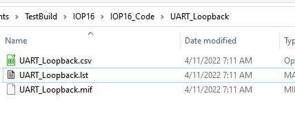
- Use Assembler to create .MIF and .LST files
- Assembler is in \TestBuild\Design_A_CPU\Assembler folder
- If Python 3 is installed double click pyAssemble_cpu_001.py to run
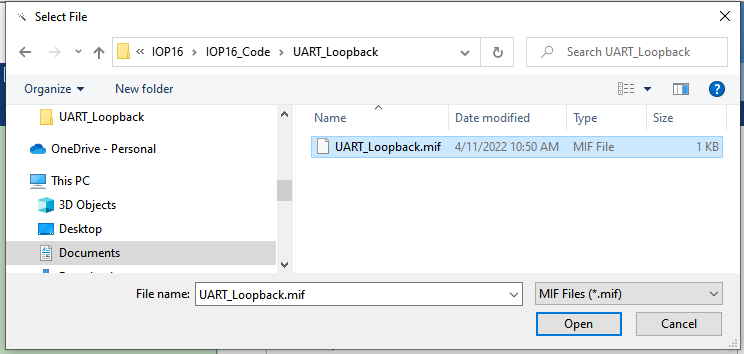
- Browse to .\TestBuild\IOP16\IOP16_Code\UART_Loopback folder
- Select UART_Loopback.csv file
- Output .MIF and .LST files will be written to folder
- Update (as above)
- Set path to new code
- Make sure to set extension to .MIF
- Resources
- Download code to FPGA
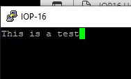
- Run puTTY
- 115,200 baud
- RTS/CTS handshake
- Type on keyboard
- Chars will loopback on serial
- LED will toggle on/off with each character
- Branches of the trees that capture these changes
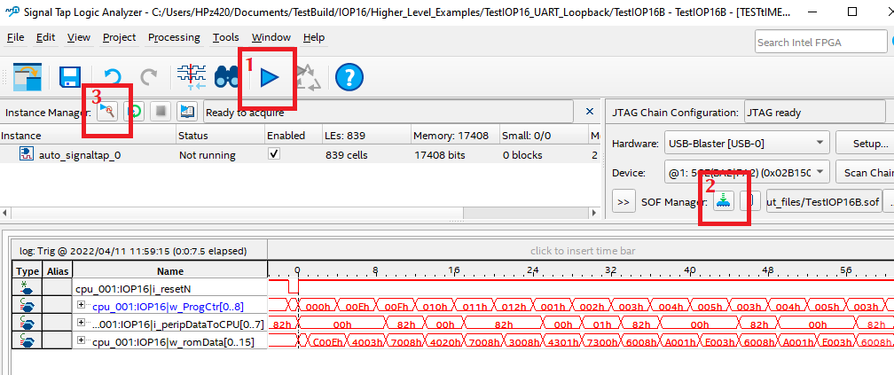
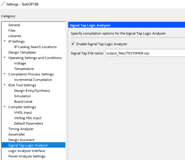
- SignalTap is an embedded Logic Analyzer
- Can be used to debug designs
- Right click on device Settings
- Select .stp file
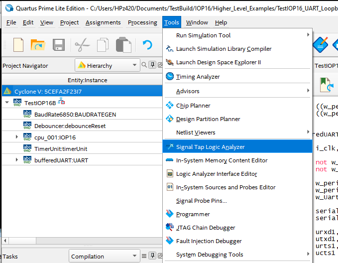
- Select Tools, Signal Tap Logic Analyzer
- Add nodes
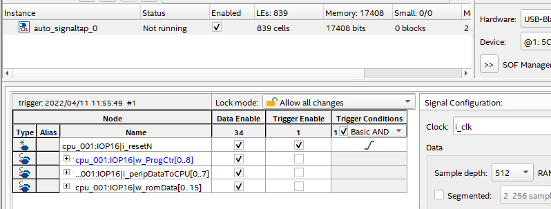
- Compile
- Download
- Start capture
- Press reset to trigger