Building your own Setup - dogerber/temperature_gradient_microscopy_stage GitHub Wiki
The present setup is tailored to the kind of experiment I needed it for and the microscopy stage we have available. Any other user will probably need a different geometry, so I'll only summarise the design ideas behind rather than being specific about the design.
A short description of the parts used with some notes why they were chosen
- Arduino Mega ($50)
- Arduino Mega Proto Shield Rev3 ($6) - Makes it easy to replace the Arduino Mega if it gets burned.
- OLED Breakout Board - 16-bit Color 1.5" w/microSD ($50)
- Adafruit OLED 128x64 ($20)
- Motor driver Pololu DRV8834 ($9)
- LM4040 ($8)- For a constant and known voltage supply for the voltage divider.
- Analog-to-digital converter ADS1115 ($15)
- 3x Thermistors Amphenol MC65F103AN (3x $10), if using other Thermistors, adapdt the code accordingly
- 3x Reference Resistors 30 kOhm (high accuracy and low temperature dependance
- 8x 10 kOhm Resistors
- Dual Motor Pololu Driver VNH5019 ($100)
- 2x Peltier devices (2x $50) ( CUI Devices, CP604060395 )
- Linear actuator (Nanotec LGA201S06-A-TDBA-038 ) ($ 130) - desired small stepsize, small size and large travel
- 1 Power switch, 2 buttons, 1 5-way joystick
- One low and one high power supply, depending on motor and Peltier device choice, see below
- Cable connectors, wires
- 4x 1uF Capacitor, 1x 100 uF Capacitor
- Piezo Buzzer
- Custom made stage head (see below)
- EPDM O-rings
- Plastic screws (low thermal conductivity)
- Custom made water cooling loop (see e.g. Heating cooling circulator or commercial GPU water coolers)
- Custom made enclosure
- Connector for signal cable Binder Mini Connector Plug 14 Contacts, it would be better to use D-Sub cables
- Connector for power cables: Mega-Fit Molex 4-pin and Mega-Fit Molex 2-pin.
Approximate total cost of (non-custom) parts: $481
The wiring diagram can be found here: Schematic, Breadboard view, Fritzing file.
Schematic

PIN connections as list
- 4 VNH5019 - M1A
- 5 VNH5019 - M1B
- 6 VNH5019 - M1ENABLE
- 7 VNH5019 - M1PWM
- 8 VNH5019 - M2A
- 9 VNH5019 - M2B
- 10 VNH5019 - M2ENABLE
- 11 VNH5019 - M2PWM
- 12 BUZZER-PIN
- 22 DRV8834 - DIR
- 23 DRV8834 - STEP
- 24 DRV8834 - M0
- 25 DRV8834 - M1
- 26 DRV8834 - Sleep
- 30 Button - OK
- 31 Button - cancel
- 32 Joystick - Left
- 34 Joystick - Up
- 35 Joystick - Down
- 36 Joystick - Push ? (not used)
- 37 Joystick - Right
- 38 TFT_DC
- 40 SD_CS CCS on display
- 41 TFT_CS
- 42 OLED_DC
- 43 OLED_CS
- 50 MISO
- 51 MOSI
- 52 SCK, Clock
- SCL, SDA (I2C): for ADS1115 (temperature measurement)
Signal cable pinout

Old:

I set the current limiting of the DRV8834 to 0.6 A which was enough for the actuator used here. A tutorial on how to do this can be found here.
The small OLED display needs to be modified to work in SPI mode. For this, the traces J1 and J2 need to be cut at the back. Note that there is a printing error on the board saying that open is for I2C mode, which is wrong. More details about this can be found here.
The setup needs power for the Peltiers, the linear actuator and the controller box. The Peltiers can operate the fastet with a high voltage, however the Arduino and actuator can only handle limited Voltages. Therefore I split the power into two with
- High Power Supply for Peltiers (19 V, 16 A)
- VNH5019: max. 12 A, max. 24 V
- Peltiers: max 6A, max. 23 V
- Low Power Supply for Linear actuator and Arduino (9V, 5 A)
- Arduino Mega: 7-12 V
- DRV8834: 1.5 A / 2.5-10.8 V
Never connect the USB cable and power the Arduino through the low power line (Power Button ON), as this can damage the Arduino Mega.
Power wire connections
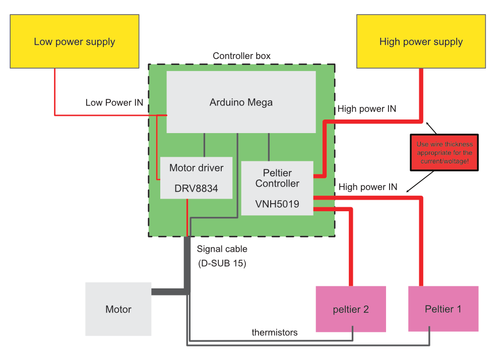
If you use any other parts then specified above, make sure that no maximum Voltage / Ampere restricitons are violated. Check especially the power requirements / allowances for all power sockets, peltier devices and motors, as well as the allowance stated above if using these parts. Futhermore it is important to use the correct wire thickness when working with high Ampere currents. For a guide on this see here. If any of these precautions are neglected it is likely that the device will set itself on fire!
If you are using different Motors than specified here, make sure to adapt the code and wiring. A stepper motor is probably the type you need (sometimes already combined to be called a linear actuator). For a general introduction of stepper motors see here.
Make sure all thermistors are in good thermal contact with the material (i.e. with thermal paste) they are supposed to control and are secured in place. If a thermistor losens itself, the feed-back loop will start to increase the power for the peltiers to the maximum level which can be dangerous for the equipment and the operator. The controller has no way of detecting if the thermistor is in the right place. Also make sure that the thermistor for the cooling circuit ("Cooling T" on screen, T_cooling_plate in code, A3) is actually in firm contact with the cooling circuit (e.g. the metal block that the coolant flows through). This is an important safety feature, as it will detect a thermal runway of the cooling. This can happen if the cooling is insufficient or broken, or if the peltiers start to overshoot (as written above). The controller box will disable peltier control (i.e. no power is supplied to the peltiers at all), if the cooling ciruit is to hot. It will also disable peltier control if any of thermistors are disconnected, broken, or measure temperatures outside the temperature range specified in the code (default: T_MIN = -45 °C, T_MAX = 40 °C).
Make sure that the Peltier devices are connected with the right polarity, change the cable polarity when it cools instead of heats. Also ensure that the two peltier devices are in contact with the correct temperature sensor.
Always test your setup when you modify it. Run extensive programs under realistic conditions and check for proper function and safety. Are there no water leaks? Does nothing heat up over time?
CAD files are available on the public Onshape Document. CAD .step files can be downloaded from here directly. Technical drawing can be downloaded here.

An important parameter is the overall weight of the stage, as it must be below the maximum allowed weight of the Microscope stage.
- Humidity protection: This is crucial to limit condensation on the copper blocks when operating at temperatures below room temperature. Condensation can decrease image quality or prevent sample movement. The humidity protection here is optimized for a copper block spacing of 2.2 mm, at which it fits tightly. Any opening should be further closed with sticky tape or foam. Especially at the opening towards the translation frame it makes sense to have some kind of lip to close the slit down while still allowing the translation frame to be moved.
- Copper block (top): This makes sure the sample is surrounded by the same temperature on both sides to make the temperature gradient as 1D as possible. This should be made from copper in to have good thermal conductivity from the lower base to the top, as it can only be thermally connected far from the window of observation in between the copper blocks.
- Sample: The current design is optimized for standard microscopy glass slides 50x24 mm and maximum height of 1 mm (depending on the spacer)
- Translation frame: Should fit tightly with the sample geometry.
- Linear actuator: Moves the sample relative to the applied temperature gradient. The coupling to the frame is made with a weak clamp, so if there's any resistance (i.e. when the frame freezes to the copper block) the motor can slide past the frame and will not be damaged. The maximum travel range of the motor should be marked on the cooling backplate as well as the middle in order to calibrate the movement and preventing a movement out of range (which can damage the actuator)
- Spacer: Thermal connection between the top and bottom copper part. Shoudl be as small as the sample geometry allows. This can easily be exchanged
- Copper block (bottom): This has space for two samples next to each other (one position below the top copper blocks and one next to it). This allows for ice nucleation on the uncovered position (usually done with a "cold finger", e.g. liquid nitrogen cooled cotton swab), after which the sample can be pushed to the covered position. The thermistors are located in the covered position as close as possible to the typical observation window. The copper blocks should be as thin as they can be machined (while still allowing for a channel inside them to hold the thermistors), as this limits how close the microscope objective can approach the sample. Only microscope objectives with a working distance larger than the thickness (+ the distance one wants to move into the sample + sample wall thickness) of the lower copper block can be used. Low thermal conductiviy screws must be used to connect the copper block to the cooling backplate (to not cause a thermal short).
- Peltier device: Optimized for large possibly temperature difference (as in steady opertion little heat flow is expected) and geometry as close as possible to the copper block (bottom).
- Cooling connection: The cooling must be sufficient to keep the backplate at a constant temperature and this must be tested extensively at realistic conditions.
- Cooling backplate: This design depends on the microscope stage opening. The current design was made for a 160x110 mm opening "Universal insert" I-3091. A copperplate can be added between Peltier device and cooling circuit to ensure tightness (even if the peltier device shoud crack).
Stage head Assembly Notes:
- Thermal paste should be applied with a Razor blade. It is very important that the thermal paste layer thickness is similar on both sides in order for the copper blocks to perfectly align. If they are not aligned properly the sample can not be moved across the blocks.
- It is recommended to use some alignment tool (e.g. 3D-printed T-piece) to make the copper blocks parallel towards the opening between them.
- Screws need to be tightened very slowly and carfully to not break the Peltier device.
- After assembly the setup must be tested for stability and tightness for several hours under realistic conditions.
Make sure to measure the resistors you build into the controller box as precisely as possible and update the values R_Ref* in the code. Temperatue is determined by measuring the resistance of the thermistors and converting this into a temperature. In order to check the measurement the resistance of resistors should be checked. Measurement noise can be reduced by either adding appropriate capacitors, averaging measurements and shielding the wires. If the correct resistance is measured, the temperature measured should also be checked. Best practise is to use an ice bath or a calibrated reference thermometer.
The temperature in the copper blocks is not necessarily the temperature in your sample cell. To measure the temperature in the sample cell a small thermistor can be connected to the third temperature channel (T3) and placed in the sample cell during operation. It is important to note, that for small spacings between the copper blocks, the two temperatures can influence each other.
The PID loop can be checked by connecting a USB cable, running the Arduino Serial Plotter (ctrl+L) and enabling the option Settings/Output T on the controller (make sure any other Serial communication is disabled). The plotter will then show the set and actual temperature values. The PID variables can be changed in Settings/Pgain, Igain and Dgain (they will reset to the hard coded values when the controller is restarted). There are many ways to tune a PID loop, this is the way I did it:
- turn Igain and Dgain to 0
- Turn Pgain up until the temperature oscillates continuously around the target value
- Turn Pgain down until this is not the case anymore
- Turn Igain up until the signal reaches the target within reasonable time
- Turn Dgain up to reduce any oscillation.
To see the performance enable the Setting Settings/Output T to... and connect through USB (make sure to put the power switch in the off position). Then open an ARDUINO IDE on the computer and open the Serial plotter (CTRL+L) to see the live performance of the setup. The variables can be changed on the running control box under Settings/PID. However they will reset to the values in the code, when the device is restarted. So once you know the correct values, also update the code values.
The performance is always a tradeoff between speed, precision and acceptable overshoot. It is worth noting, that the peltier heats much faster than it cools. I personally optimized for cooling performance and little overshoot.
The motor stepsize should be measured on a microscope and updated in the code for the Arduino. For this:
- Put stage head on microscope and focus on something that will be moved by the motor.
- Set stepsize to 1 at Settings/motorstepsize [um], so that the motor moves in whole motor(micro)steps
- Move by a (large) amount of motor steps, measure the translation this causes on the microscope.
- calculate the stepsize from this and update the code.
- The variable "mot_maxPos" must also be adjusted to prevent movement out of the range of the linear actuator.