LCR 48in electric mowing deck guide - directedmachines/customer-support GitHub Wiki
The LCR comes with an optional electric mowing deck, mounted on the 3PT hitch. This guide describes best practices and maintenance.
Before beginning any mower related procedure/maintenance follow the Safety Checklist
- LCR in position, deck at desired height (no deck removal for procedures on this page)
- E-Stop the LCR (to disallow manual activation of drive or mower)
- Switch motor disconnect switch to off (to ensure LCR cannot drive)
- Unplug mower motor from external tray Anderson connector "Aux1" (to ensure mower cannot spin)
- Unplug 2x actuator molex (to ensure hitch cannot raise or lower)
The 48" Mower deck comes with a ribbed belt that is attached to 8 pulleys, providing power to the three blades underneath. A tension pulley, with a spring and eye bolt, provides enough lateral force on the belt to prevent slipping. Pay attention for wear on flat side such as scratches, fraying on the edges, as well as cracking between teeth or missing teeth on the pulley. Keep pulleys and belt, especially the drive pulley attached to the motor, clear of debris; clean off grass, sticks, dirt, and moisture using a brush, blower, or by hand.
Click here to expand instructions dropdown
- Pull out plastic connector
- Raise mower deck using 3PT Hitch
- Lower Mower onto crate until there is slop in the chains holding the Mower
- Keep connected to one side for safe keeping
- Remove 2x Pins From Hitch
- Slide Lift Arms off Hitch
- Reconnect Pins in Place for Safe Keeping
- BX94 V Belt, Rubber, 5/8" x 97" OC
- Take a photo or create a diagram to record the route of the belt. Note the direction of the teeth on the belt, and which pulleys the belts rests upon.
- Remove locknut on eyebolt attached to the motor bracket.
- Remove belt carefully, one pulley at a time.
- Slide belt under motor pulley, with teeth facing the pulley.
- Pull tight, slide belt onto right-under-motor pulley, repeat on other side. The flat side of the belt is resting on these pulleys.
- Route the belt onto the rest of the pulleys, in a counter-clockwise motion. On the double pulleys, the belt will rest on the lower pulley. The route of the belt should look like the cardinal directions of a compass or a four-leaf clover.
- On the tensioning pulley, there should be a spring attached to an eye bolt with a locknut. Attach the eye bolt through the hole on the bracket that is attached to the motor, and secure using another locknut. Please review the following videos:
https://photos.app.goo.gl/pdcpYdWaDgXxQh5a8s
- When a belt has popped off its pulleys but is undamaged, it can be remounted onto the pulleys without tools.
- Get the belt seated on the correct path for all pulleys and all spindles except for one of the outer spindles, where the belt should be in between the top and bottom V's of the spindle.
- Use both hands to pull the belt along and walk the belt into the bottom V of the outer spindle until the belt is fully mounted correctly onto the spindle.
- Review the reattaching core belt without tools video for a demonstration.
Click here to expand instructions dropdown
- Blade should remain on mower through this process
- Eye Protection
- Ear Protection
- Gloves
- Clean Blade and area near it of grass dirt and other debris

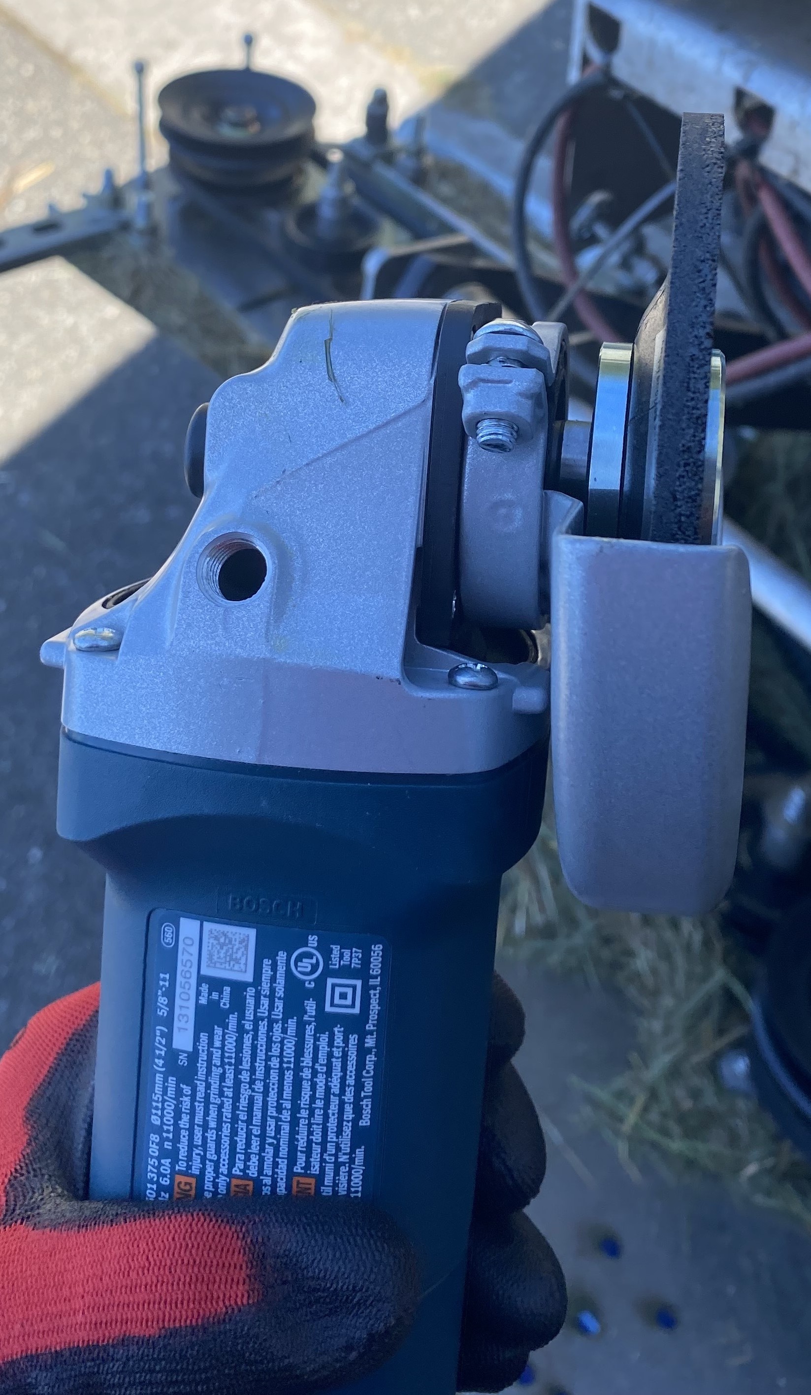
- Grinding side of disk should face toward the handle
- Park LCR next to power source where you can plug angle grinder into outlet, follow safety list at top of page (e-stop, unplugging, etc)
- WIRING CHECK! Do not jam or stress posts on motor or add tension to mower cable for entirety of procedure.
- Disconnect the mower deck's Aux1 Anderson connector from tray.
- Lower the deck to disconnect the turnbuckles' carabiners from the mower deck.
- Lift one side of the deck enough to place a piece of stackable material (i.e. wood block ) under the left/right edge of the deck and the ground.
- Repeat the above step to the opposing side of the deck. Continue, switching sides each time, until the deck is 1-2 feet off the ground.
- Raise the lift actuators enough to give slack to the chain connection that attach the 3PT hitch to the lift arms.
- With safety gloves, squat in front of the supported deck to lift the front of the deck until it is tilted nearly 90° up and standing on its back anti-scalping wheels.
- Support the standing mower deck by propping it up with 2x 26-30" strut channel.
- Place wood blocks between the ground and blades to prevent their rotation while sharpening.

- Video Example Here
- Disk side up, use angle grinder to sharpen top of blade. ONLY THE TOP of the blade should be worn down to sharpen the edge.
- Ideally we are trying to achieve a 30-35 degree angle from the plane of the spindle/mower deck.
- The blade should be no sharper than a butter knife.
- You want to use a consistent angle and never round the sharpened cutting part of the blade.
- Ideally, control your grinder so that sparks are flying in the direction the sharp edge is pointing (note that this changes as you use different quadrants of the angle grinder, so try to be consistent)


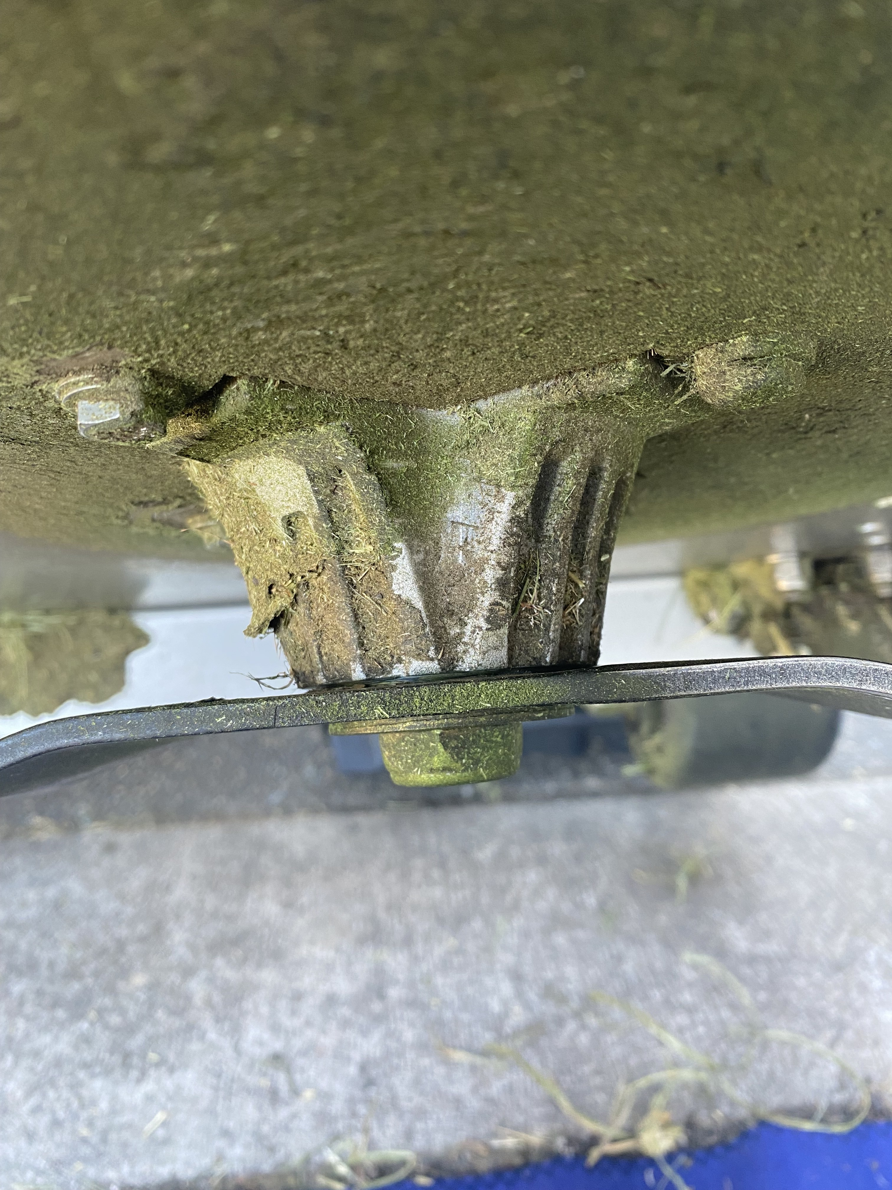
- Pull off grass tangled around spindle base

Click here to expand instructions dropdown
Unloading mower decks from shipping crates using the vehicle or robot mounted swivel crane.
Click here to expand instructions dropdown

- Use Manual UI on your phone, **set translation to .20**, then, carefully position the LCR parallel the mowing deck - Approach mowing lower lift arms so they are right under the stub shafts of the 3PT hitch base - Add lubricant inside lift-arm ball, and on stub shaft then push towards shaft base. - Manually move/wiggle the LCR slowly on one hand, **whilst pushing** the lift-arm with another hand - If lift arm ball joint is being difficult, use a rubber mallet and tap the lift-arm in the stub shaft
Click here to expand instructions dropdown
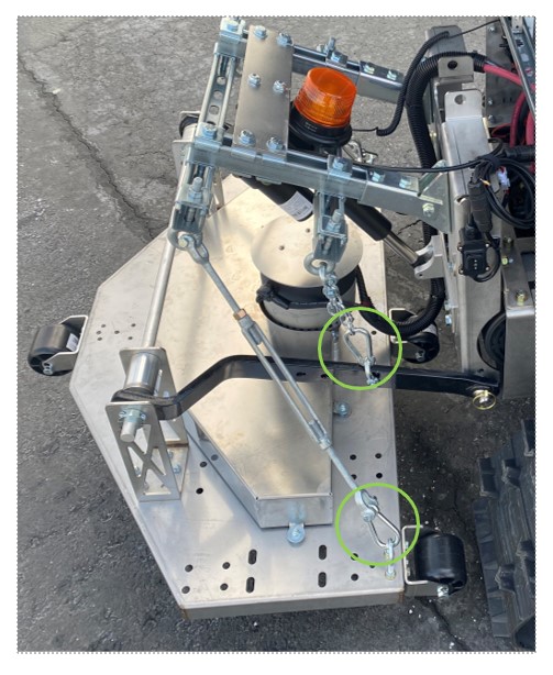
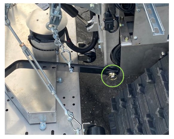
Mower decks are connected to 3PT hitch cores and are supported by two pairs of essential hardware: short-length chains for lift arm supports, and either long-length chains or turnbuckles for lift deck supports. Adjusting either of these lift supports significantly affects the mower deck's position. Refer to the visualization image below for a clearer understanding of the deck leveling dynamics.

- Modifying lift-arm support (blue highlight on chain) affects deck's **front **height level.
- Modifying lift-deck support (orange highlight on chain or turnbuckle) affects deck's **rear **height level.
- Adjusting both supports together changes the overall deck height.
Maintaining the correct mower deck adjustments is crucial for achieving optimal mowing results across various terrains and types of vegetation. Below are the recommended adjustments based on different conditions:
When dealing with sloped decks, where the front is elevated, follow these steps:
- Raise the lift-arm support by one or two chains.
- Drop the lift-deck support by at least two chains.
Pros:
- Effectively handles high-volume vegetation growth, even at 0.50 aux power.
- Performs well on sloped terrains
Cons:
- Increased risk of deck flipping when driving on the caster side.
- Caution: Avoid using this deck adjustment near solar panels.
For even or flat decks, make adjustments based on your judgment by balancing the chain levels to achieve the best fit.
Pros:
- Provides efficient mowing for medium-low vegetation growth.
- Safest option for caster-side driving.
Cons:
- More challenging to tackle high vegetation growth; therefore,
- Requires higher aux power when dealing with significant vegetation growth.
- When mowing near solar panels, prioritize safety at all times. Avoid using slope-adjusted decks in such areas. If utilizing the flat deck adjustment, it's advisable to use the maximum height when mowing areas with high vegetation growth.
Click here to expand instructions dropdown
- Instructions given for Reduction Motors, but work with Mower Motors as well. Skip portions called out for right motor only - they are not relevant to mowers.
- Motor Terminal Repair
- keep clear of mower while troubleshooting
- If you need to get close or inspect parts of mower you MUST follow safety checklist at top of page to deactivate mower
- Turn motor disconnect switch to OFF so you can test aux without robot moving
- Once safe protocol and conditions are established, you may proceed
Click here to expand instructions dropdown
If the belt keeps coming off the pulleys, check
- Is tensioner eyebolt, attached to idler arm pulley properly tightened?
- Is idler arm pivot bushing / bolt secure (not wobbly) on mowing deck?
- Are idler pulley bearings in place, healthy? Check for seized or damaged bearings
If the extension belt keeps coming off the pulleys, if the belt is over-tensioned, or if the extension spring is constantly breaking, check:
- Is the extension flush against the core deck?
- If there is a gap between the core and the extension, loosen the bolts holding the extension and bring it closer to the core deck

During mows, it is common to get caught up in tall foliage that can tug on the mowing deck and add stress to certain parts causing them to bend. One of the common areas are the Lift Arm Brackets (X-Wings). If these brackets become bent, you can bend them back to their original state quite easily using another LCR, a personal vehicle, or other large mobile objects.
First ensure that the mowing deck is disconnected from the LCR so there is no chance that deck will swing around off the ground.
Once on the ground determine which direction the brackets need to be bent to be restored to their original shape.
Counter force will need to be applied to each of the brackets arms in order to bend them back into place, as well as ensure the deck stays stationary. This can be accomplished by attaching chains to the lift arm, or the lift arm bracket itself. Then apply force in both directions to bend the bracket back to acceptable position. Note image below.

Force should only need to be applied in a single direction here. You can use the caster side of the LCR to back into the lift arm bracket and provide force to start pushing it back into position. Just be aware of colliding with the auxiliary motor. Note image below.


Ensure lift arm brackets are back to an acceptable position.
Check the following from the Drive Train Troubleshooting Page:
- check if motor is spinning but spindle is not
- tension on all belts good
- jammed spindles or dull blades see above
- Ensure the LCR is enabled in the manual ui
- SSH into the LCR and check for stale host-specific override files for actuators-navigators-default
The mowing deck energy draw is related to the belt tension. If belts are too tight, the mowing will draw too many amps and overheat the motor and belt.
- For 48" decks, the no load draw, operating at 50%, over low grass, should be below 50A
- For 96" decks, the no load draw, operating at 50% should be below 120A
Test:
- Using Manual UI with deck raised so it is touching NO GRASS or foliage
- set AUX power to 50%
- enable AUX
- Very very slowly (we just want aux coming on, but not moving) move robot, so AUX is on.
- Continue mowing for 1 minute
- Using the telemetry UI page in the fleet management UI for the robot, search for "amps" and verify draw for AUX motor. This can be done on the telemetry page of the robot itself
If the amps are higher than the values above, follow the stalled motor guide
There is a visual tree to follow linked here
- Diagnosing:
- Expected Warnings / Alerts:
- "AXLE_AUX_MOTOR disconnected (check panel switch, wiring, motor brushes)" Fleet Alert
- "power draw too low on AUX motor" AGT UI Warning
- "AXLE_AUX_MOTOR Controller Disconnected" Manual UI Warning
- Telemetry shows near zero amps, but voltage across AUX is as expected (ie, 30V for 60% AUX power)
- Expected Warnings / Alerts:
- Troubleshooting:
- Continuity check:
- (+ Motor Lead to + MC Lead) and (- Motor Lead to - MC Lead)
- Continuity expected: True
- If False:
- Inspect the blade contacts inside the Anderson plug.
- Inspect RED and BLACK cable from motor leads to MC + / - leads
- Inspect motor + / - leads. If a lead is broken, follow the Repair Broken Motor Lead
- Inspect the blade contacts inside the Anderson plug.
- (+ Motor Lead to + MC Lead) and (- Motor Lead to - MC Lead)
- Continuity check:

- You MUST follow the Safety Checklist before beginning any in-person mower maintenance.
- Diagnosing:
- Expected Warnings / Alerts:
-
"AXLE_AUX_MOTOR HW fault" Fleet Alert
- "Over current detected on AXLE_AUX_MOTOR" Fleet Alert
- "possible stall, current draw high on AUX motor" AGT UI Warning
-
"AXLE_AUX_MOTOR HW fault" Fleet Alert
- Telemetry shows stall amps (220 or above for several seconds) under little to no load
- Expected Warnings / Alerts:
- Troubleshooting:
- If remote, attempt to run the motor in reverse to dislodge possible clogged grass
- In the Manual UI, turn AUX power to -50% and enable AUX. Move robot forward about 10 meters
- Return to autonomous control and check if AUX amps have returned to normal. If not, continue the troubleshooting below
- Use hands + gloves to move the belt, making sure the deck can freely rotate all spindles
- Check under side of spindles and blade hubs for clogged grass
-
- Adjust spring tension if the belt is hard to move
- Check under side of spindles and blade hubs for clogged grass
- If deck is clear mechanically, check for a failed motor or a motor + / - cable shorting to the frame
- Check AUX cables and motor leads for any damage
- Continuity check:
- (+ Motor Lead to Motor Frame) and (- Motor Lead to Motor Frame)
- Continuity expected: False
- If True: If no cable damage was found, the motor has likely failed
- (+ Motor Lead to Motor Frame) and (- Motor Lead to Motor Frame)
- Test mower in person at various Aux speeds (50%, 65%, 75%)
- The motor speed not changing as the aux speed changes is indicative of a failed motor
- A constant high amps in telemetry even as the motor ramps up and down is indicative of a failed motor
- Check AUX cables and motor leads for any damage
- If remote, attempt to run the motor in reverse to dislodge possible clogged grass


- Diagnosing:
- Telemetry shows ZERO volts and ZERO amps, but power to AUX is expected
- Troubleshooting:
- MC gate driver is not turning on, so there is zero PWM output
- MC is likely damaged. Check for corrosion, post images of MC