4ch 10A Mod Relay Overview - dimaatmelodromru/techdoc GitHub Wiki
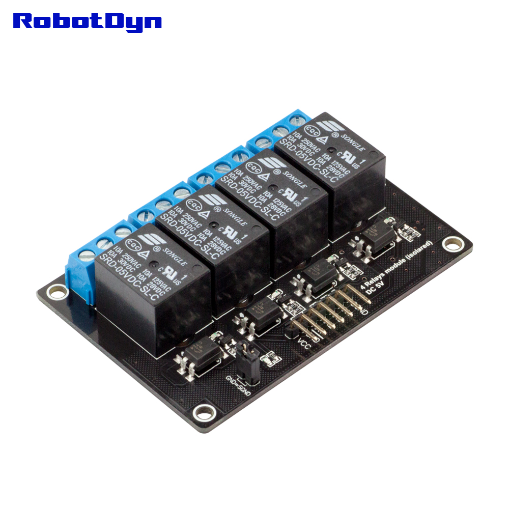
The relay module is a 4-channel logically operated switch that allows you to turn on or off a circuit that operates at voltage and/or current much higher than a microcontroller could handle, 110-220V AC / 10A for this particular module. This relay is galvanically isolated, i.e., there is no electrical connection between the low voltage circuit operated by the microcontroller logic and the high power circuits. The relay protects MCU from AC cirquit. However, if you wand to use common ground for MCU and the signal ground make sure the jumper is placed on the GND=SGND pins, remove otherwise. This module has 4 relays with three connections each named NC, COM, and NO. Depending on the input signal each relay will switch from CLOSED (connected) at LOW to OPEN (disconnected) at HIGH.
- On-board EL817 photoelectric coupler with strong photoelectric anti-interference isolating ability
- 4 on-board 5V, 10A / 250VAC, 10A / 30VDC relays
- Endurance: 100000 cycles
- Module has diode current protection, short response time
- PCB Size: 77.5mm x 52.5mm

- SGND: ground
- IN1: control signal
- IN2: control signal
- IN3: control signal
- IN4: control signal
- GND: ground
- VCC: 5V DC


void setup(){
 pinMode(5, OUTPUT);
 pinMode(6, OUTPUT);
 pinMode(7, OUTPUT);
 pinMode(8, OUTPUT);
}
void loop(){
 digitalWrite(5, LOW);
 digitalWrite(6, LOW);
 digitalWrite(7, LOW);
 digitalWrite(8, LOW);
 delay(2000);
 digitalWrite(5, HIGH);
 digitalWrite(6, HIGH);
 digitalWrite(7, HIGH);
 digitalWrite(8, HIGH);
 delay(2000);
}The components to be used are:
- Microcontroller (any RobotDyn MCU or arduino-compatible controller)
- 4 channel 5V 10A relay module
- Pin connectors
- Breadboard
- USB cable
- 4 AC lamps
- Connect the components based on the figure shown in the wiring diagram using pin connectors. VCC and COM pin is connected to the 5V power supply, GND pin is connected to the GND, IN1 and IN2 pins are connected to the digital I/O pin. Pin number will be based on the actual program code.
- After hardware connection, insert the sample sketch into the Arduino IDE.
- Using a USB cable, connect the ports from the microcontroller to the computer.
- Upload the program.
- Connect the 4 AC-powered lamps to the AC power ground and to phase line via the relay using the NC connector of each relay Be very careful working with AC circuits as high AC power can injure or kill
- Power up the MCU and observe the lamps switching on and off for 2 seconds repeatedly