Soldering and assembling - dilshan/avr-hv2 GitHub Wiki
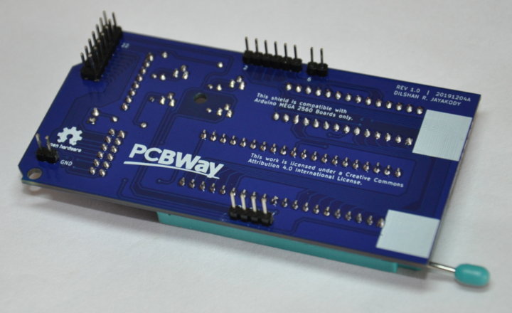
To overcome soldering difficulties this project uses standard, through-hole type components. All the parts of this PCB can solder using regular 30W - 40W soldering iron, or by using a general-purpose soldering station.
Note:
-
While assembling the PCB, make sure to solder all Arduino pin headers from the top side of the PCB.
-
To avoid short-circuits we recommend placing insulation tapes to the whites squares marked at the bottom side of the PCB.
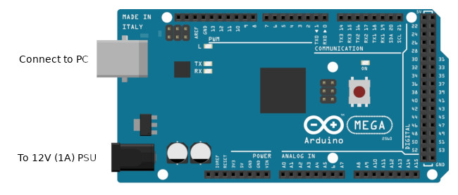
Preparing Arduino Mega 2560 board
Before connecting the AVR-HV2 shield, make sure to load the Arduino sketch into the board. Arduino IDE version 1.8, or a newer version can be used to transfer a sketch into the board.
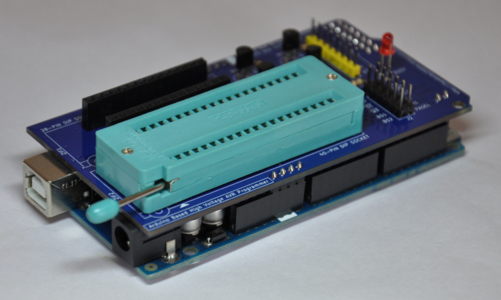
After loading the sketch, disconnect the board from the PC and install the AVR-HV2 shield into the Arduino Mega board. As a next step, connect 12V power supply unit and USB cable into the Arduino board.
Once the power is applied, wait for 10 - 15 seconds to boot the firmware. Also, before using the programmer, close the Arduino IDE to release the allocated COM port.